Communication
FPΣ User's Manual
204
• Settings for COM port 1 (FPG-COM1, FPG-COM2)
No. Name Set value
412
COM port 1 - communication mode Program controlled
413 COM port 1 - communication format
Data length: 7 bits/8 bits
Parity: None/Odd/Even
Stop bit: 1 bit/2 bits
End code: CR/CR+LF/None/ETX
Start code: No STX/STX
415
COM port 1 - baud rate 2400–115200bit/s
416
COM port 1 - receive buffer starting address 0–32762 (initial value: 0)
417
COM port 1 - receive buffer capacity 0–2048 words (initial value: 2048 words)
• Settings for COM port 2 (FPG-COM2, FPG-COM4)
No. Name Set value
412
COM port 2 - communication mode Program controlled
414 COM port 2 - communication format
Data length: 7 bits/8 bits
Parity: None/Odd/Even
Stop bit: 1 bit/2 bits
End code: CR/CR+LF/None/ETX
Start code: No STX/STX
415
COM port 2 - baud rate 2400–115200bit/s
418
COM port 2 - receive buffer starting address 0–32762 (initial value: 0)
419
COM port 2 - receive buffer capacity 0–2048 words (initial value: 2048 words)
NOTE
In PROG mode, the TOOL port is automatically set to MEWTOCOL-COM mode
even if program controlled mode has been selected. This way it is always
possible to communicate in PROG mode with a programming software like
FPWIN Pro.
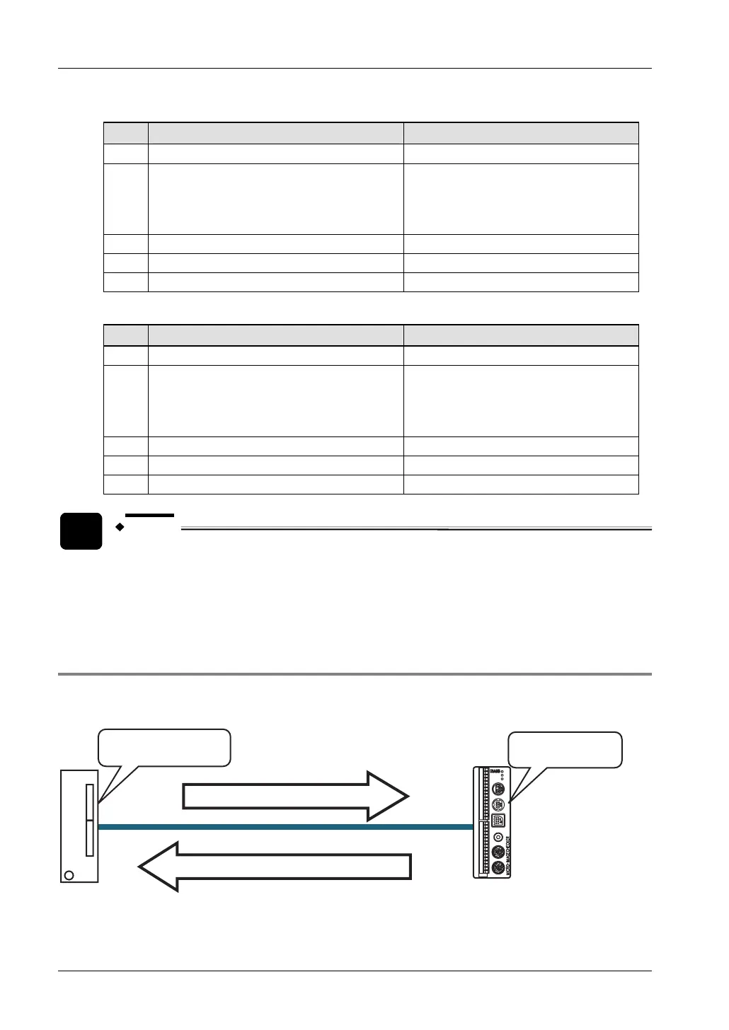
8.6.6.1 1:1 Communication with Micro-Imagechecker
The FPΣ and Micro-Imagechecker A100/A200 are connected using an RS232C cable. The
results of the scan are stored in the data registers of the FPΣ.
Start command "%S
C
R
" is sent
Scan result "1012345
C
R
" is received
Communication mode:
Program controlled
communication
Communication mode:
Normal mode
Micro-Imagechecker
A200/A100
PLC
1:1 communication between the FPΣ and a Micro-Imagechecker