Communication
FPΣ User's Manual
228
System register settings
Station settings
No. Name
#1 #2 #3 #4
41
1)
Link registers - Send/receive area - Number of words shared by all linked
PLCs
128 128 128 128
44
Link registers - Send area - Start sending from this word address 0 40 80 0
45
Link registers - Send area - Number of words to send 40 40 48 0
1)
The value of this system register must be identical for all stations.
When link areas are allocated as shown above, the send area of station no. 1 can be
transmitted to the receive areas of stations no. 2, 3, and 4. Also, the receive area of station
no. 1 can receive data from the send areas of stations no. 2 and 3. Station no. 4 is allocated
as a receive area only and can receive data from stations no. 1, 2, and 3, but cannot send
data to other stations.
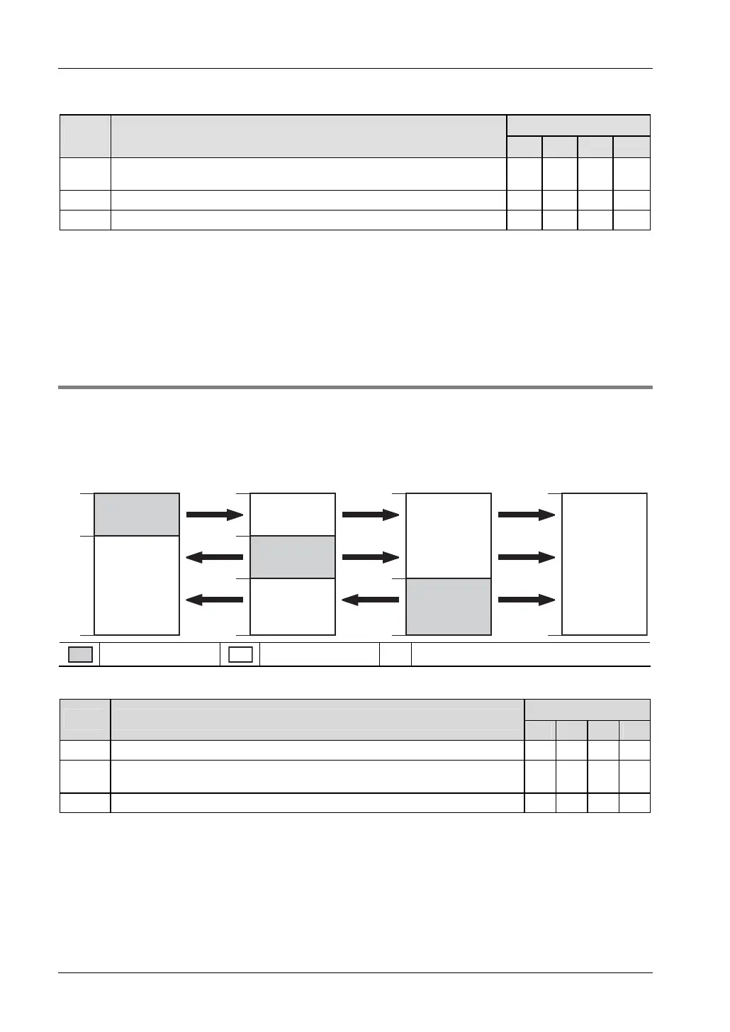
8.7.2.2 Example for PLC link 1
Set system register 46 to "Reverse" to use PLC link 1. See "PLC Link 0 and 1 Allocation
Setting" on page
232.
Link relay allocation
WL64
83
84
127
WL64
83
84
127
WL64
127
WL64
127
103
104
103
104
#4#1 #2 #3
#1
#2
#3
#1
#2
#3
#1
#2
#3
Send area
Receive area # Station number of PLC
System register settings
Station settings
No. Name
#1 #2 #3 #4
50
1)
Link relays - Send/receive area - Number of words shared by all linked PLCs 64 64 64 64
52 Link relays - Send area - Start sending from this word address 64 84
10
4
64
53 Link relays - Send area - Number of words to send 20 20 24 0
1)
The value of this system register must be identical for all stations.