FPΣ User's Manual
8.7 PLC Link
227
Using PLC link 1
You can either use PLC link 0 or PLC link 1. Set system register 46 to "Reverse" to use PLC
link 1. See "
PLC Link 0 and 1 Allocation Setting" on page 232.
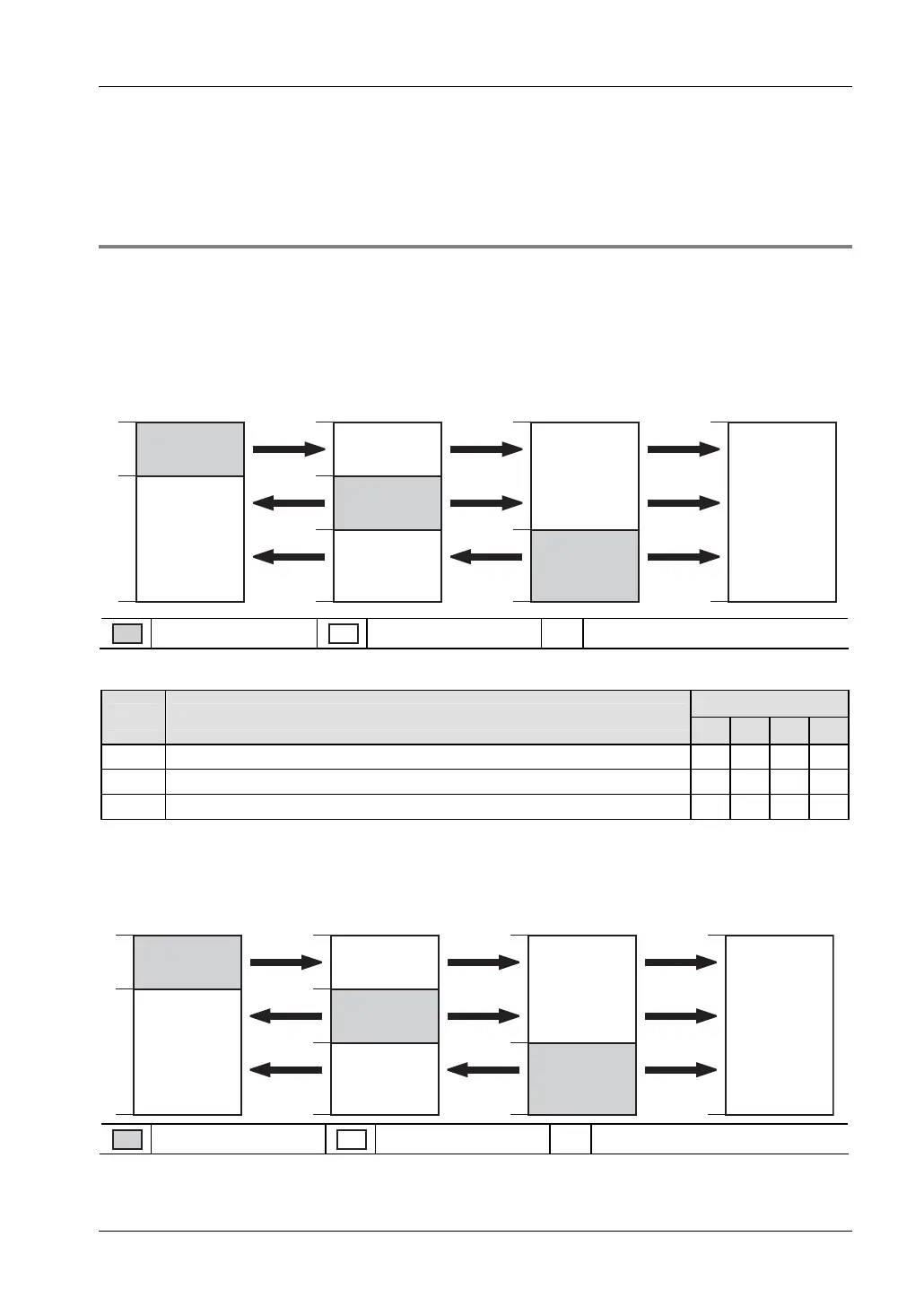
8.7.2.1 Example for PLC link 0
The PLC link areas are divided into send and receive areas. The link relays and link registers
are transmitted from the send area to the receive area of a different PLC. The link relays and
registers in the receive area on the receiving side must be within the same area as on the
sending side.
Link relay allocation
WL0
19
20
63
WL0
19
20
63
WL0
63
WL0
63
39
40
39
40
#1 #4#2 #3
#1
#2
#3
#1
#2
#3
#1
#2
#3
Send area
Receive area # Station number of PLC
System register settings
Station settings
No. Name
#1 #2 #3 #4
40
1)
Link relays - Send/receive area - Number of words shared by all linked PLCs 64 64 64 64
42
Link relays - Send area - Start sending from this word address 0 20 40 0
43
Link relays - Send area - Number of words to send 20 20 24 0
1)
The value of this system register must be identical for all stations.
Link register allocation
LD0
39
40
127
LD0
39
40
127
LD0
127
LD0
127
79
80
79
80
#4#1 #2 #3
#1
#2
#3
#1
#2
#3
#1
#2
#3
Send area
Receive area # Station number of PLC