FPΣ User's Manual
7.4 Pulse Output Function
137
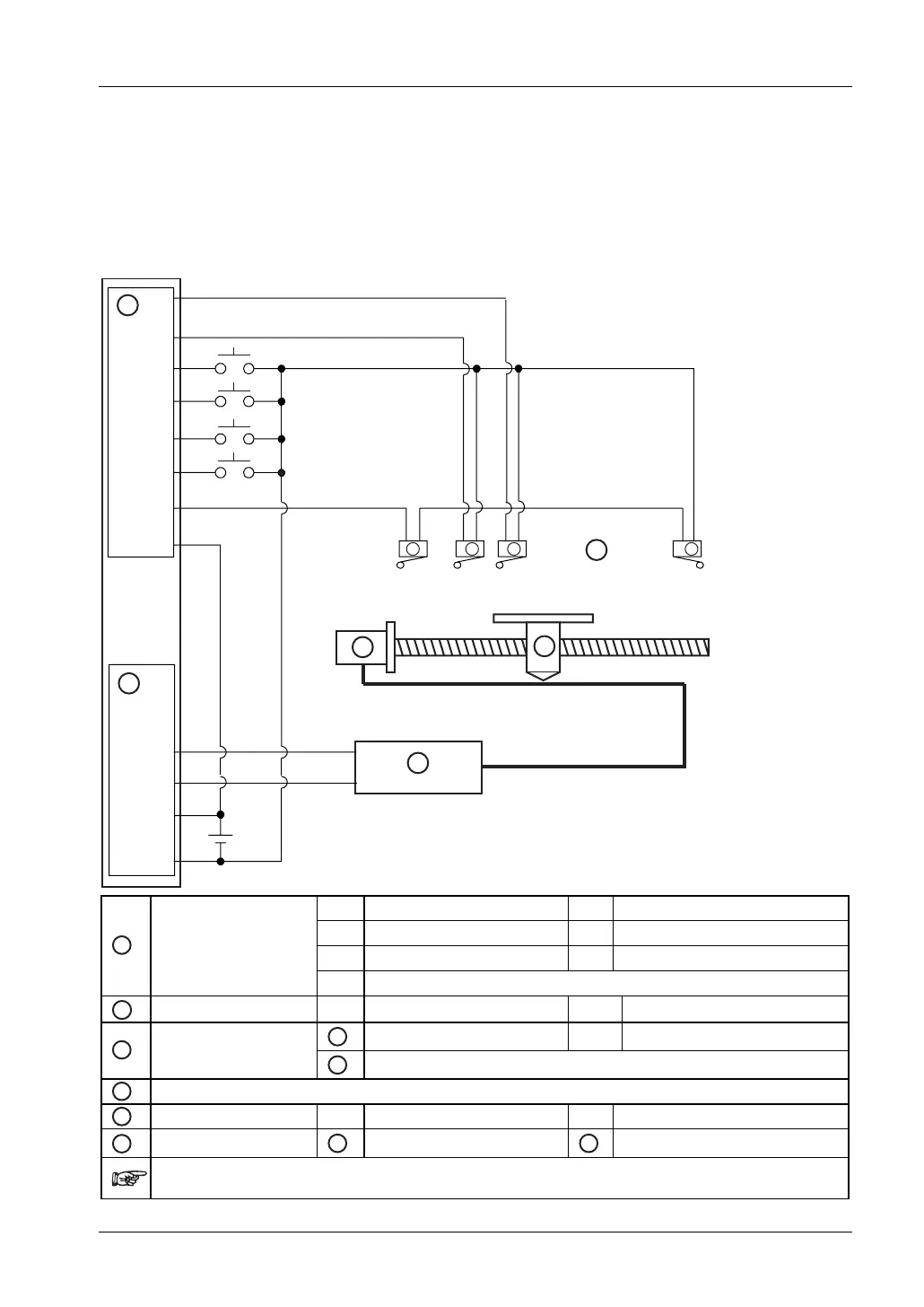
Wiring diagram for examples 1–3
The wiring diagram below applies to the following examples:
• Example 1: trapezoidal control (see page
139)
• Example 2: home return in a backward direction (-) (see page
142)
• Example 3: home return in a forward direction (+) (see page
143)
X0
X8
X9
XA
X2
XB
XD
COM
Y0
Y1
+
-
B
ab a b
C
( - )
( + )
24 V DC
A
D
E
F
X0
Near home sensor
XA
Home return start (channel 0)
X2
Home sensor
XB
Home return start (channel 2)
X8
Positioning start (+)
XD
Overrun
A
PLC: Input terminal
X9
Positioning start (-)
B
PLC: Output terminal Y0 CW pulse output Y1 CCW pulse output
1
CW input
COM
Common input
C
Motor driver
2
CCW input
D
Stepping motor
E
Moving table (+) + side (-) - side
F
Switches
a
N.O. contact
b
N.C. contact
If necessary, connect a resistor between PLC outputs and motor driver inputs. Please refer to the
manufacturer's documentation for correct wiring of the motor driver.