FPΣ User's Manual
8.5 MEWTOCOL-COM
179
It is recommended to connect the computer to the TOOL port of the FPΣ. A connection cable
(order no. AFC8513D) with a 5-pin mini-DIN connector and a 9-pin Sub-D connector is
available.
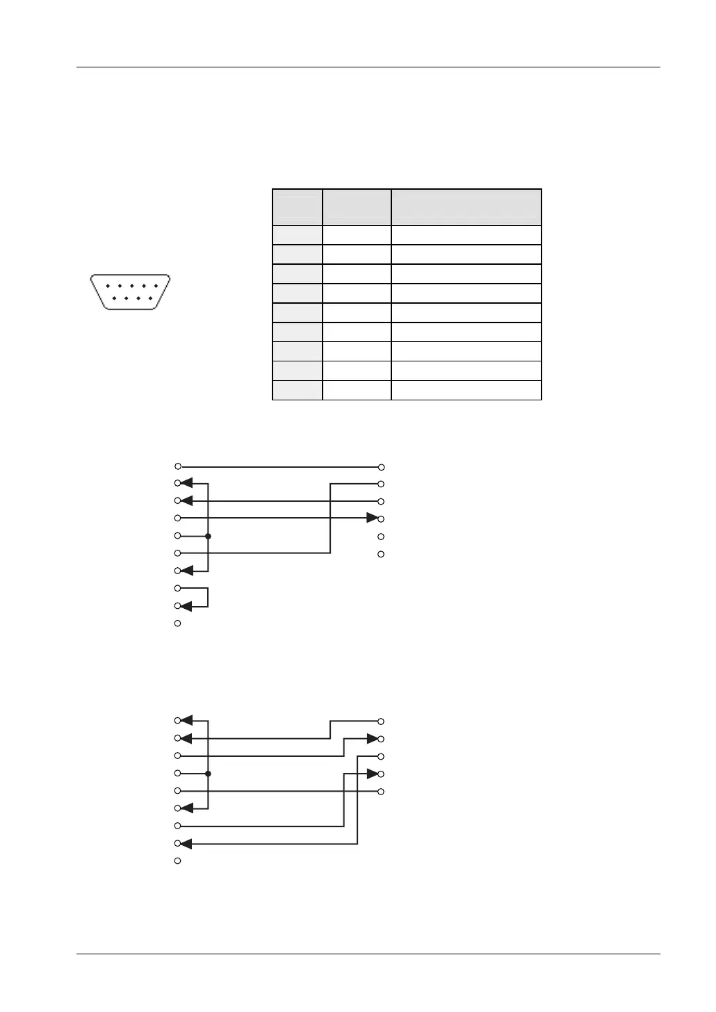
The TOOL port or the 5-pin terminal of the communication cassette is connected to a 9-pin
Sub-D connector on the computer. The Sub-D connector has the following pin layout:
Pin Name Description
1 CD Carrier Detect
2 RXD Receive Data
3 TXD Transmit Data
4 DTR Data Terminal Ready
5 GND System Ground
6 DSR Data Signal Ready
7 RTS Request To Send
8 CTS Clear To Send
51
96
9-pin Sub-D male connector
on computer
9 RI Ring Indicator
Wiring diagrams
• Using the TOOL port
SG
SD
RD
1
2
3
4
5
6
7
8
9
CD
RXD
TXD
DTR
GND
DSR
RTS
CTS
RI
1
2
3
4
5
FG
FG
Left: computer, right: FPΣ
For the pin layout of the TOOL port, see "
Parts and Functions" on page 16.
• Using the 1-channel RS232C type communication cassette (FPG-COM1):
SG
SD
RD
RS
CS
1
2
3
4
5
6
7
8
9
CD
RXD
TXD
DTR
GND
DSR
RTS
CTS
RI
Left: computer, right: FPΣ