FPΣ User's Manual
8.7 PLC Link
237
Station settings
System
register
Name
#1 #2 #3
41
Link registers - Send/receive area - Number of words shared by all linked PLCs 128 128 128
44
Link registers - Send area - Start sending from this word address 0 40 80
45
Link registers - Send area - Number of words to send 40 40 48
Setting the highest station number
Station settings
System
register
Name
#1 #2 #3
47
Highest station number in network 3 3 3
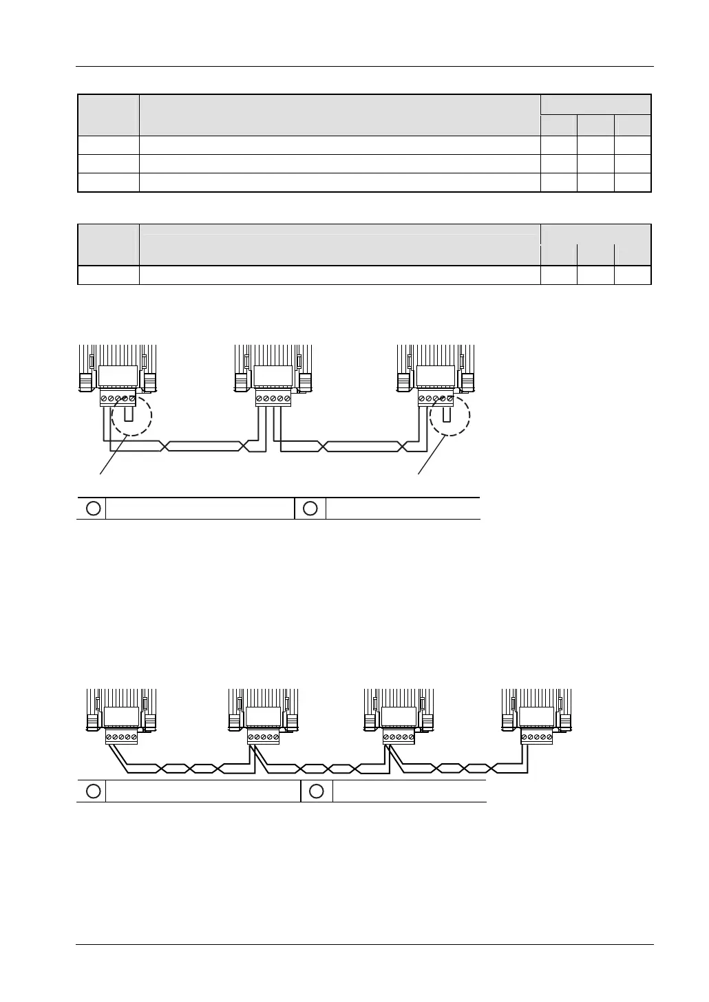
Connection diagram for FPG-COM3
FPΣFPΣ FPΣ
1
Bridge between E and (-)
2
Transmission line
Bridge the E terminal and the free (-) terminal on the first and on the last station of the
transmission line to terminate the data bus. (See "
FPG-COM3: 1-Channel RS485 Type" on
page
160.)
Connection diagram for FPG-COM4
To terminate the data bus use the DIP switch on the cassette of the last station of the
transmission line.
FPΣ
FPΣFPΣFPΣ
1
SW1-1 must be ON
2
Transmission line
Set SW1-1 to ON on the first and on the last station of the transmission line to terminate the
data bus. (See "
DIP Switch Setting on FPG-COM4" on page 162.)
Programming example
For each of the three stations, a PLC program is required. In order to have consistent data in
all stations, the common data should be kept in the GVL of a common library. This user library
must be loaded on each station: