17 CIRCUIT OPERATION (HANDSET)
17.1. Construction
The circuit mainly consists of DSP and RF part as shown in the block diagram.
17.1.1. DSP: IC201
Function
•
• •
• Battery Low, Power down detect circuit
•
• •
• Ringer Generation
•
• •
• Interface circuit
RF part, Speaker, Mic, LED, Key scan, LCD, Headset
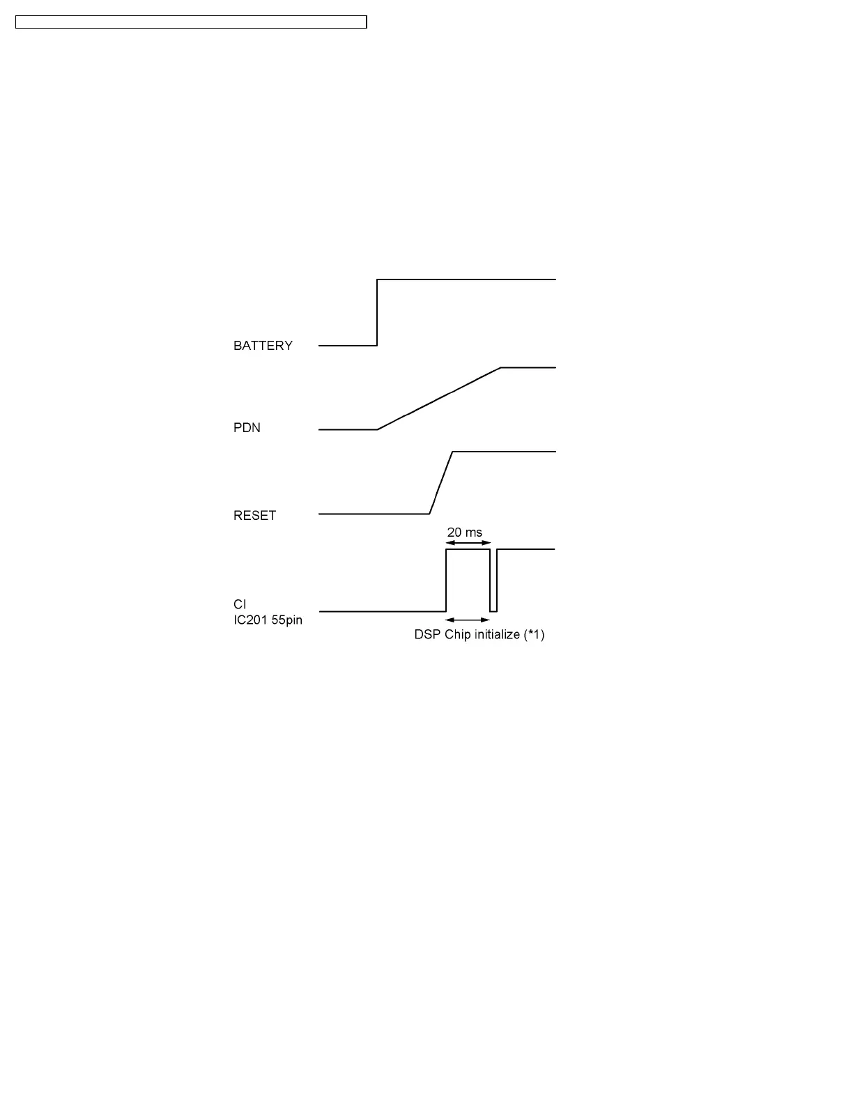
Initialize
Note:
(*1) The initializing time of the DSP chip is 20ms under normal conditions.
17.1.2. RF part
Mainly voice signal is modulated to RF, or it goes the other way.
17.1.3. EEPROM: IC241
All setting data is stored.
ex: ID code, user setting (Phonebook, Caller ID data)
74
KX-TG5631S / KX-TG5632M / KX-TG5633B / KX-TGA560S / KX-TGA560M / KX-TGA560B
 Loading...