7
ENGLISH
1. GENERAL
This booklet briefly outlines where and how to install the air conditioning system. Please read over the entire set of instructions for the
indoor and outdoor units and make sure all accessory parts listed are with the system before beginning.
The installation of pipe-work shall be kept to a minimum.
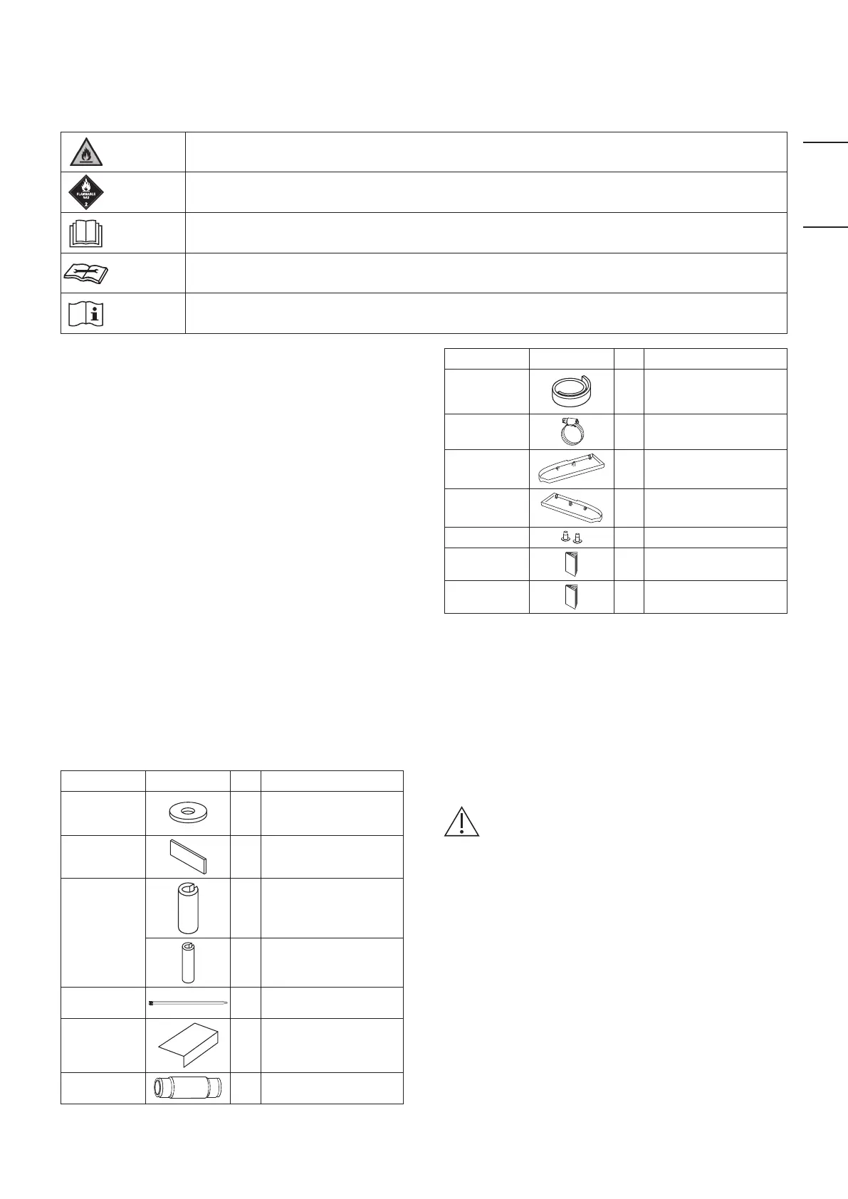
WARNING
This symbol shows that this equipment uses a flammable refrigerant. If the refrigerant is leaked, together with
an external ignition source, there is a possibility of ignition.
CAUTION
This symbol shows type of flammable refrigerant contained in the system.
CAUTION
This symbol shows that the Operating Instructions should be read carefully.
CAUTION
This symbol shows that a service personnel should be handling this equipment with reference to the Technical
Manual.
CAUTION
This symbol shows that there is information included in the Operating Instructions and/or Installation
Instructions.
1-1. Tools Required for Installation (not supplied)
1. Flathead screwdriver
2. Phillips head screwdriver
3. Knife or wire stripper
4. Tape measure
5. Carpenter’s level
6. Sabre saw or keyhole saw
7. Hacksaw
8. Core bits
9. Hammer
10. Drill
11. Tube cutter
12. Tube flaring tool
13. Torque wrench
14. Adjustable wrench
15. Reamer (for deburring)
1-2. Accessories Supplied with Unit
The accessory parts are supplied inside the indoor unit.
Open the air-intake grille of the indoor unit and take out a
package of accessories.
See the section “3-2. Preparation Before Installation”.
Table 1-1 (
Ceiling
)
Part Name Figure Q’ty Remarks
Special
washer
4
For temporarily
suspending indoor unit
from ceiling
Drain insulator
2 For drain hose joint
Flare insulator
1 For gas tube joint
1 For liquid tube joints
Clamper
6
For flare insulator and
wiring
Full-scale
installation
diagram
1
For positioning
installation
Drain hose
1
For main unit + PVC pipe
joints
Part Name Figure Q’ty Remarks
Insulating
tape
2
For gas and liquid tubes
flare nuts
Hose band
1
For drain hose
connection
Side cover (R)
1
(Packed in carton box)
For right side
Side cover (L)
1
(Packed in carton box)
For left side
Screw
2 For side cover (L/R)
Operating
Instructions
1
Installation
Instructions
1
1-3. Type of Copper Tube and Insulation Material
If you wish to purchase these materials separately from a local
source, you will need:
1. Deoxidized annealed copper tube for refrigerant tubing.
2. Foamed polyethylene insulation for copper tubes as
required to precise length of tubing. Wall thickness of the
insulation should be not less than 8 mm.
3. Use insulated copper wire for field wiring.
Wire size varies with the total length of wiring.
See the section “4. ELECTRICAL WIRING” for details.
CAUTION
Check local electrical codes and regulations before
obtaining wire.
Also, check any specified instructions or limitations.
1-4. Additional Materials Required for Installation
1. Refrigeration (armored) tape
2. Insulated staples or clamps for connecting wire (See your
local codes.)
3. Putty
4. Refrigeration tubing lubricant
5. Clamps or saddles to secure refrigerant tubing
6. Scale for weighing
00_301038_All.indb 7 2018/6/11 15:42:46