9
ENGLISH
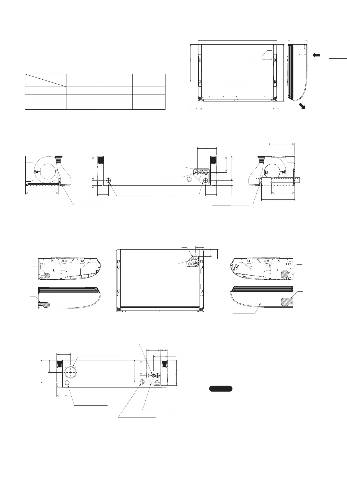
(2) Refrigerant tubing • drain hose position
39
39
90
90
86
187
267
267
196
196
131
70
216
Rear (Figure shows view from front)Left side
Left drain position
Closed with rubber stopper
at time of shipment.
Left drain position Right drain position
(Liquid tubing •
Gas tubing)
Right side
Gas tubing
Liquid tubing
Right drain position
(3) Unit opening position (Refrigerant tubing • drain hose • power inlet port • remote control wiring inlet port)
74
R50
*1
*1
*1
*2
88
104
*1
90
61
120
123
123
114
104
185
131
196
105
Left-side drain hose
outlet port
Top outlet port
Right-side drain
hose outlet port
Side cover
Outside air intake duct
connection port
(ø100, cutout)
Rear outlet port (Figure shows view from front)
Remote control wiring
and inter-unit wiring inlet port
Left-rear side drain
hose outlet port
(cutout)
Cover of tubing hole
Power inlet port
*1 Use a compass saw, jig saw or similar tool and cut along
the indented portion of the side cover and make a hole
inside the cover.
*2 When removing the refrigerant tubing from the upper
side, cut along the indented portion and pass the tubing
through the hole.
N OTE
Be sure to use sealing putty to seal off the opening to
prevent dust.
3. HOW TO INSTALL THE INDOOR UNIT
■
Ceiling Type (Type T2)
3-1. Required Minimum Space for Installation and
Service
(1) Dimensions of suspension bolt pitch and unit
Length
Type
A B C
36, 45, 50 911 960 235
60, 71 1226 1275 235
100, 125, 140 1541 1590 235
Unit: mm
A
265
190
24.5 24.5
B
690
C
Air intake
Air discharge
(Suspension bolt pitch)
(Suspension
bolt pitch)
Unit: mm
Unit: mm
Unit: mm
00_301038_All.indb 9 2018/6/11 15:42:47