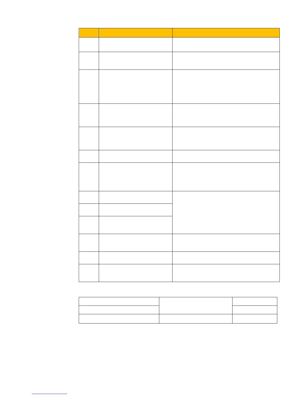
the running status, and ON signal is output.
15 Frequency arrival output
Indicating inverter runs at the setting target
frequency, and ON signal is output. See F312.
16
Overheat pre-alarm
Warning
When testing temperature reaches 80% of
setting value, ON signal is output. When
overheat protection occurs or testing value is
lower than 80%of setting value, ON signal stops
outputting.
17 Over latent current output When output current of inverter reaches the
setting overlatent current, ON signal is output.
See F310 and F311.
18
Analog line disconnection
protection
Indicating inverter detects analog input lines
disconnection, and ON signal is output refer to
F741.
19 Reserved
20 Zero current detecting output When inverter output current has fallen to zero
current detecting value, and after the setting time
of F755, ON signal is output, refer to F754 and
F755.
21 Output controlled by PC/PLC
1 means output is valid.
0 means output is invalid.
22 Reserved
23 TA\TC Output controlled by
PC/PLC
24
Watchdog token output
The token output is valid when inverter trips into
Err6.
25-29 Reserved
40 Switchover of high-frequency
performance
When this function is valid, inverter will switch
into high-frequency optimizing mode.
When F300=2, 3, F301=2, 3 and F302=2, 3 and token characteristic frequency is selected, this
group function codes set characteristic frequency and its width. For example: setting F301=2,
F307=10, F309=10, when frequency is higher than F307, DO1 outputs ON signal. When
frequency is lower than (10-10*10%)=9Hz, DO1 outputs OFF signal.

 Loading...


