48 High-frequency switchover
When this function is valid, inverter will switch into
high-frequency optimizing mode.
52 Jogging (no direction)
In the application 1 and 2, the direction of jogging
command is controlled by terminal set to 58:
direction.
53 Watchdog
During the time set by F326 elapses without an
impulse being registered, inverter will trip into
Err6, and inverter will stop according to stop mode
set by F327.
54 Frequency reset
In the application 4, if the function is valid, target
frequency will change to the value set by F113.
55
Switchover between manual run
and auto run
In the application 2, the function is used to switch
manual run and auto run.
56 Manual run
In the application 2, if the function is valid, inverter
will run manually.
57 Auto running
In the application 2, if the function is valid, inverter
will run automatically.
58 Direction
In the application 1 and 2, the function is used to
give direction. When the function is valid, inverter
will run reverse. Or else, inverter will run forward.
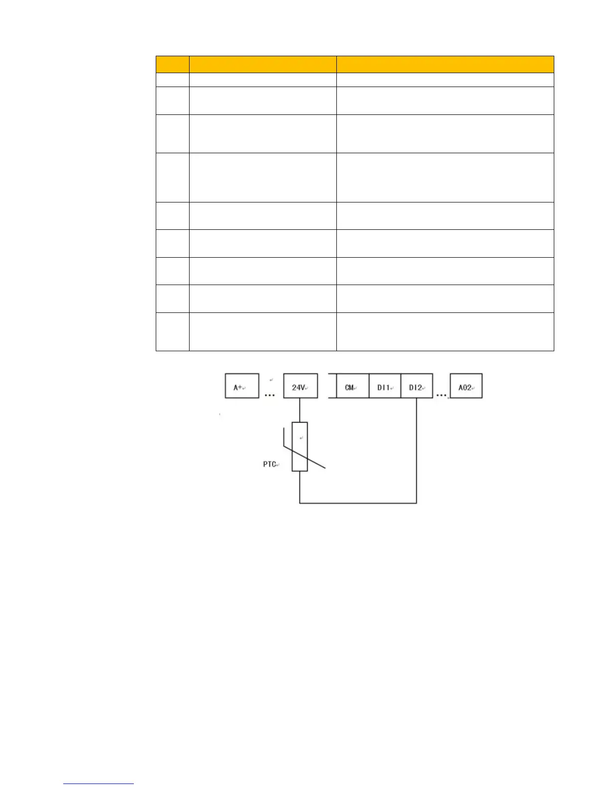
Figure 9-6 PTC Heat Protection
When the coding switch is in the end of “NPN”, PTC resistor should be connected between CM
and DIx terminal. When the coding switch is in the end of “PNP”, PTC resistor should be
connected between DIx and 24V. The recommended resistor value is 16.5KΩ.
Because the accuracy of external PTC has some differences with manufacture variation some
errors can exist, thermistor protection relay is recommended.
NOTE: To use this function double insulate motor thermistor must be used.

 Loading...


