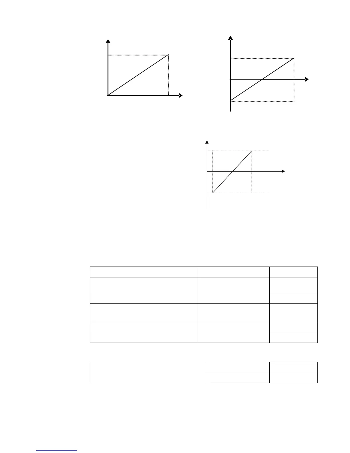
Figure 9-8 Correspondence of analog input to setting
The unit of for scaling the upper / lower
limit of input is in percentage (%). If the
value is greater than 1.00, it is positive; if
the value is less than 1.00, it is negative.
(e.g. F401=0.5 represents –50%).
The corresponding setting benchmark: in
the mode of combined speed control,
analog is the secondary frequency and
the setting benchmark for range of
secondary frequency which relatives to
main frequency is “main frequency X”;
corresponding setting benchmark for other cases is the “max frequency”, as illustrated in the
right figure:
A= (F401-1)* setting value
B= (F403-1)* setting value
C= F400
D= F402
F406 Lower limit of AI2 channel input (V)
Setting range: 0.00~F408
Mfr’s value: 0.01
F407 Corresponding setting for lower limit
of AI2 input
Setting range: 0~F409
Mfr’s value: 1.00
F408 Upper limit of AI2 channel input (V)
Setting range: F406~10.00
Mfr’s value: 10.00
F409 Corresponding setting for upper limit
of AI2 input
Setting range:
Max (1.00,F407) ~2.00
Mfr’s value: 2.00
F410 AI2 channel proportional gain K2
Setting range: 0.0~10.0
Mfr’s value: 1.0
F411 AI2 filtering time constant (S) Setting range: 0.1~50.0 Mfr’s value: 0.10
The function of AI2 is the same with AI1.
F418 AI1 channel 0Hz voltage dead zone (V) Setting range: 0~1.00 Mfr’s value: 0.00
F419 AI2 channel 0Hz voltage dead zone (V)
Setting range: 0~1.00
Mfr’s value: 0.00
Analog input voltage 0-5V can correspond to output frequency -50Hz-50Hz (2.5V corresponds
to 0Hz) by setting the function of corresponding setting for upper / lower limit of analog input. The
group function codes of F418 and F419 set the voltage range corresponding to 0Hz. For example,
when F418=0.5 and F419=0.5, the voltage range from (2.5-0.5=2) to (2.5+0.5=3) corresponds to
0Hz. So if F418=N and F419=N, then 2.5±N should correspond to 0Hz. If the voltage is in this
range, inverter will output 0Hz.

 Loading...


