Microdrive Series Instruction Manual
4201-109 Rev I
50
10, 11, 12, 13 MOTOR INFORMATION
Screen 10 MTR CUR=70A*
Description RATED (NAMEPLATE) MOTOR CURRENT
Min/Max 0.20/1.50 x I(Inverter)
Units AMPS
* This value is dependent on Microdrive current rating.
Screen 11 MTR VOLT= 415V
Description RATED (NAMEPLATE) MOTOR VOLTAGE
Min/Max 10/995
Units AC VOLTS
Screen 12 MTR FR = 50Hz
Description RATED (NAMEPLATE) MOTOR
FREQUENCY
Min/Max 10/250
Units HERTZ
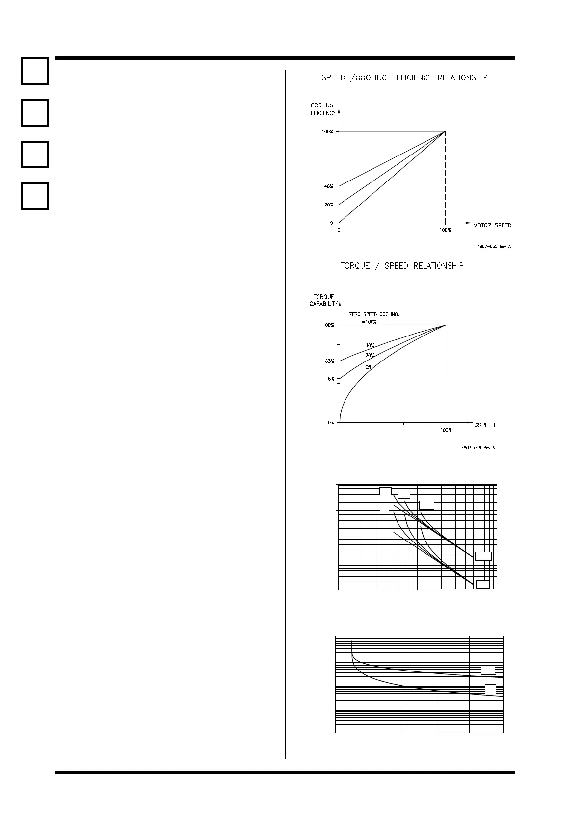
Screen 13 MTR COOL= 40%
Description MOTOR COOLING AT ZERO SPEED
Min/Max 5/100
Units %
FUNCTION To calibrate the Microdrive for the motor
being driven. Sets the correct voltage and
nominal operating frequency. Current,
frequency and the motor cooling at zero
speed parameters are used to define the
thermal model. The thermal model performs
a superior function to a thermal overload
relay since it uses this data to compensate
for differing cooling efficiencies when the
motor is operated at other than rated
frequency.
The thermal model is reset when power is
removed from the Microdrive, therefore it is
usually preferable to maintain power to the
Microdrive at all times, and use the control
inputs to stop and start the motor as
required.
Thermal sensors (PTC) mounted in the
motor windings provide ultimate protection
and are still recommended.
Where using multiple motors, each must
have the same rated frequency and voltage.
Each motor should be provided with its own
thermal protection since it is not possible for
the Microdrive to protect individual motors.
Enter the total current.
SETTING UP Enter motor rated (nameplate) parameters -
current, voltage, frequency. Estimate the
efficiency of cooling of your motor at zero
speed and enter this figure (this is very
application dependent - as a guide 4060%
is typical; where open frame, water or force
cooled motors are used, a higher cooling
efficiency will be achieved).
Motor Thermal Overload Characteristics
LOAD(%)
TIME(s)
1
10
100
1000
10000
10 100 1000
20%
0%
40%
100%
HOT
COLD
4807-118 Rev A
Microdrive Thermal Overload Characteristics
INVERTER CURRENT (%)
TIME (s)
1
10
100
1000
10000
100 110 120 130 140 150
COLD
HOT
4807-152 Rev B
10
11
12
13