Microdrive Series Instruction Manual
4201-109 Rev I
26
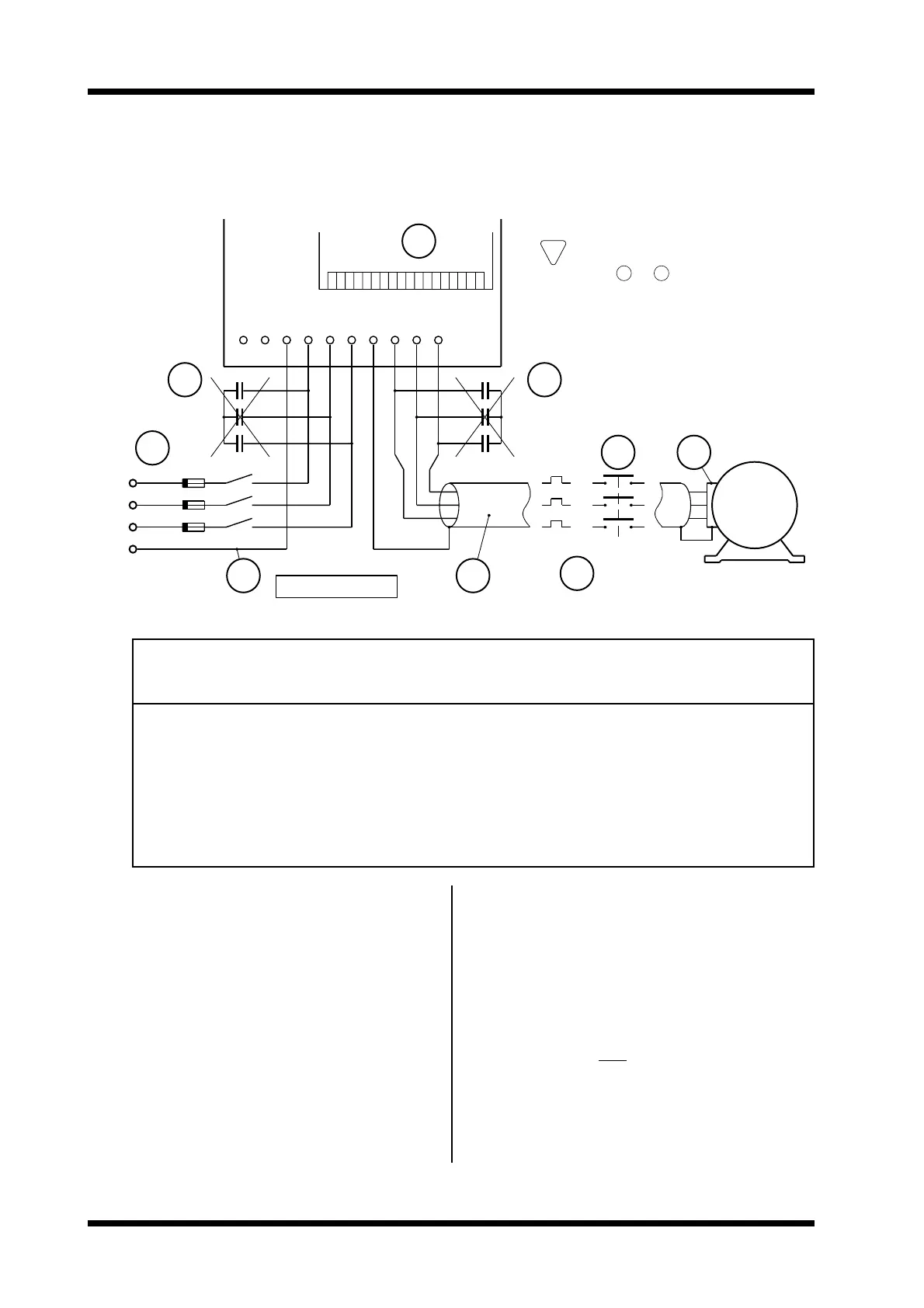
WARNING:
ENSURE SUPPLY IS ISOLATED
BEFORE WIRING UP
W
NO!
L3
E
L2
L1
4807−021 Rev E
F3
6
F1
F2
1
E
2
DC
+
−
L2L1
L3 U
EV
7
NO!
5
4
3
5
M
WARNING:
READ NOTES TO
BEFORE CONNECTING TO
POWER TERMINALS
2
!
1
8
1. Wiring Details:
UD3 RATED FUSE RECOMMENDED POWER TERMINAL
MODEL CURRENT (Q1) CABLE SIZE TERMINAL TIGHTENING
TYPE TORQUE
AA mm
2
Nm
2.5 2.5 6 2.5 SLEEVE 1.5
6.5 6.5 10 2.5 SLEEVE 1.5
10.5 10.5 16 2.54.0 SLEEVE 1.5
12 12.0 20 2.54.0 SLEEVE 1.5
16 16.0 20 2.54.0 SLEEVE 1.5
22.5 22.5 30 4.06.0 SLEEVE 1.5
31 31.0 40 6.010.0 LUG 4.0
46 46.0 60 10.016.0 LUG 4.0
60 60.0 80 25.035.0 LUG 4.0
70 70.0 80 25.035.0 LUG 4.0
be isolated before operating on the motor terminals.
6. The UD3 output switching voltage waveform can
give rise to high (capacitive) earth leakage currents.
Permanent earth connection of both the motor and
the UD3 is essential before connection to the
supply.
7. The control input circuit is configurable from the
keyboard. Be sure that you are using the correct
configuration and circuit before wiring up. Good
control circuit wiring practice should be observed.
Control wiring must be screened and run physically
separate from power wiring (at least 300mm
distance and crossing only at right angles).
8. The location and order of the power terminals
varies from model to model. Refer to the terminal
labels before connection.
2. Power factor capacitors are not required on the
UD3 input (UD3 pf = .95), and must not be
connected to the UD3 output.
3. A motor isolator or contactor may be used on the
UD3 output, but its use should be restricted to
emergencies.
4. Where radio frequency interference may be a
problem, screened cable (e.g., neutral screen, steel
conduit) must be used on the UD3 output. Bond
the screen solidly to the UD3 and motor chassis.
The output cables should be run separate from the
input cables (especially if not screened).
5. The UD3 protects the motor with an electronic
overload, so an external overload relay is
unnecessary. Where multiple motors are
attached, separate overload protection should be
applied to each motor. The UD3 or the motor must
Figure 1.4a Microdrive-3 (UD3) Recommended Power Wiring Instructions