Microdrive Series Instruction Manual
4201-109 Rev I
65
52 VOLTAGE LIMIT SLIP
Screen 52 VLT SLIP=2.0%*
Description VOLTAGE LIMIT SLIP
Min/Max 0.0/9.9
Units %
* This value is dependent on Microdrive current rating.
FUNCTION If a motor is overdriven (e.g., by decelerating
its attached load too fast) it will regenerate into
the Microdrive. Too much regeneration will
cause the Microdrive to take evasive action
(voltage limiting) by reducing the deceleration
rate as regeneration occurs.
The voltage limit slip setting is an adjustment
which is used to enhance the stability of
voltage limiting control by providing a motor slip
parameter.
SETTING UP Do not adjust this setting unless voltage limiting
is unstable. Nominally this value should be set
to the rated percent slip of the motor (see
Screen 46 to calculate this value). To improve
stability of voltage limit use a lower value. The
penalty against this is that voltage limiting will
occur at an earlier stage, thus affecting
deceleration more.
The S-curve setting (Screen 17) may also be
used to improve stability during voltage limiting.
53 NO LOAD DAMPING
Screen 53 DAMPING=0.4%*
Description NO LOAD DAMPING
Min/Max 0.0/5.0
Units %
* This value is dependent on Microdrive current rating.
FUNCTION Some motors may become unstable and appear
to surge when operated at light load and at
certain speeds. The damping term may be
introduced to eliminate this tendency.
SETTING UP Do not adjust this value unless light load
stability problems exist.
Increase setting to improve stability. Increasing
the setting too far may induce instability.
The setting is nominally equal to 20% of the
calculated percentage motor slip (see Screen
46).
No load damping introduces very small output
frequency variations (typically <0.1 Hz). If
absolute fixed output frequency is a specific
requirement of your application, set to 0.0%.
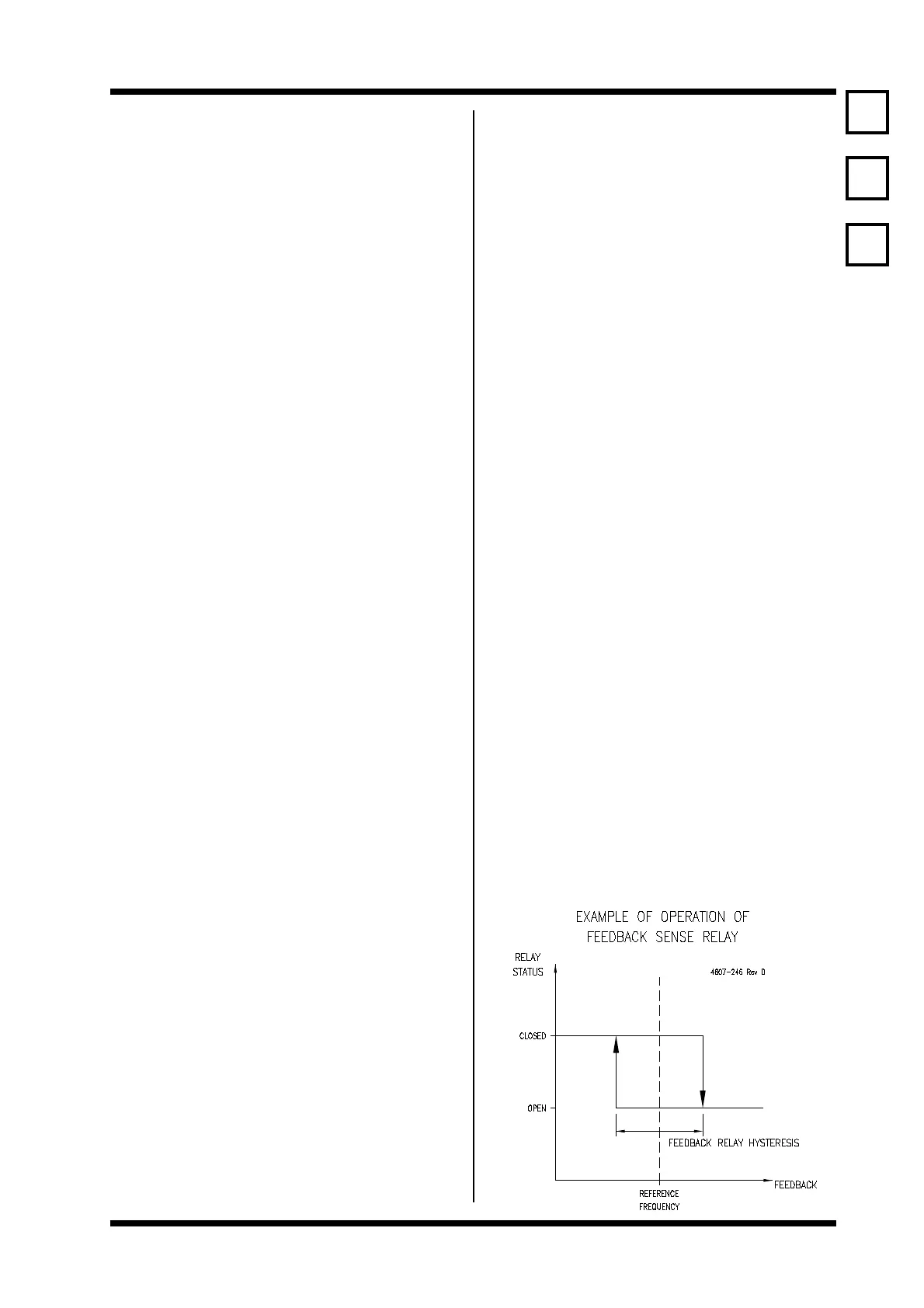
54 FEEDBACK SENSE RELAY HYSTERESIS
Screen 54 FB RLY = 10.0 Hz
Description FEEDBACK SENSE RELAY HYSTERESIS
Min/Max 0/200
Units HERTZ
FUNCTION T o set the operating points of the feedback
sensing relay. This relay is useful to show that
a feedback process is operating correctly and
is at its setpoint.
A feedback input signal higher than the
reference setpoint plus half the hysteresis
frequency set in this function will de-energise
the selected relay.
When the feedback drops below the reference
minus half the hysteresis frequency the relay
will re-energise.
Equations for relay output:
Relay open
Feedback > reference + ½ hysteresis
Relay closed
Feedback < reference ½ hysteresis
SETTING UP The feedback sense relay hysteresis is not
used unless the Microdrive is configured for
process control (feedback) operation.
Set the relay hysteresis to the value required by
your feedback process.
Configure the relay output using Screens 67,
68, 69.
EXAMPLE Reference = 50 Hz
Hysteresis = 10 Hz
Relay open
Feedback > 50 Hz + 5 Hz
Relay closed
Feedback < 50 Hz 5 Hz
Note: Refer example in Appendix 4D - Application
Example - Constant Pressure Pumping with
Automatic Start/Stop Control.
52
53
54
 Loading...