Microdrive Series Instruction Manual
4201-109 Rev I
64
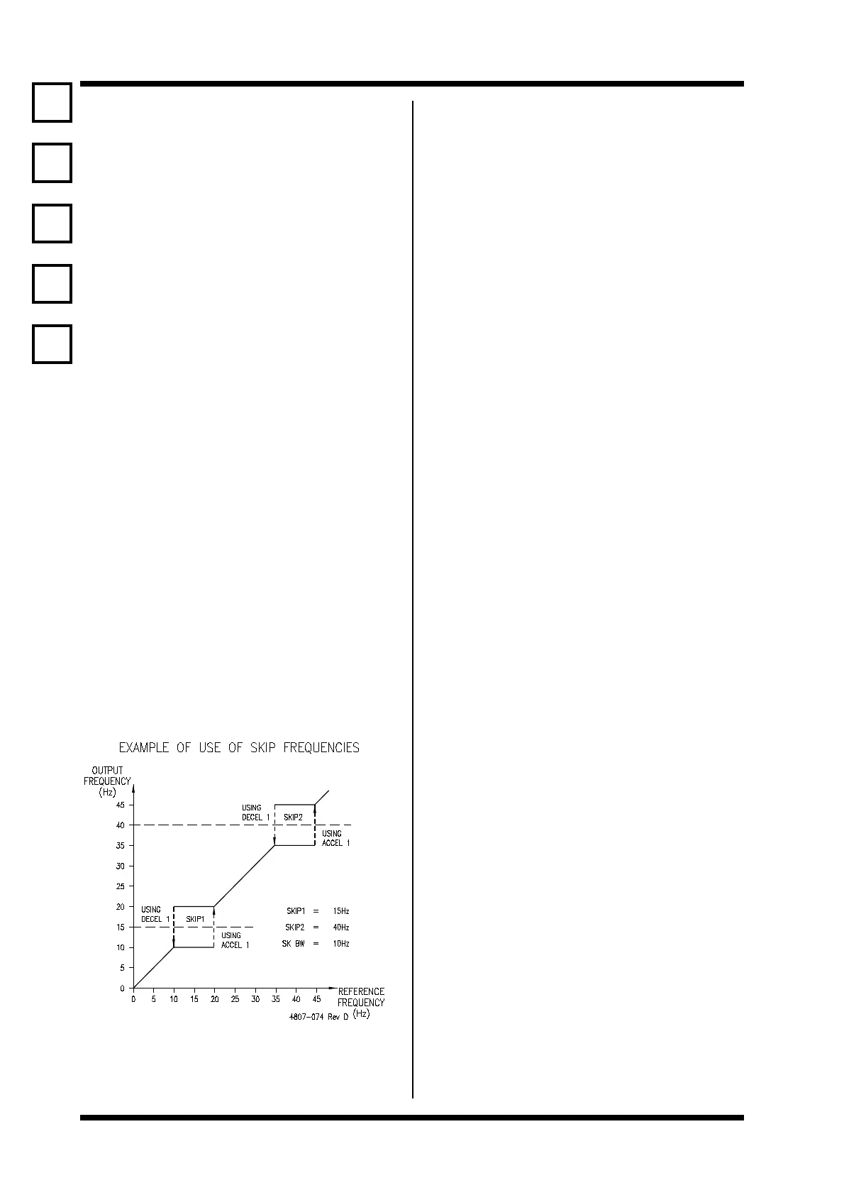
47,48,49 SKIP FREQUENCIES
Screen 47 SKIP 1 = + 0.0Hz
Description SKIP FREQUENCY 1
Min/Max -200/+200
Units Hz
Screen 48 SKIP 2 = + 0.0Hz
Description SKIP FREQUENCY 2
Min/Max -200/+200
Units Hz
Screen 49 SK BW = 0.0Hz
Description SKIP BAND WIDTH
Min/Max 0.0/10.0
Units Hz
FUNCTION To provide two zones of frequencies that
cannot be set. The object is to provide keep
out areas of operation which may be selected
so that natural mechanical system resonances
can be avoided.
Skip frequencies 1 and 2 define the middle of
each skip zone. The skip band width defines
the width of the zones.
SETTING UP Complete other commissioning first. Determine
points, and breadths of any (two) mechanical
resonances in your system. Enter skip
frequencies and desired band width. Do not
overlap skip zones unless only one zone is
required. If only one skip zone is required,
define the same frequency for both zones.
To turn off skip frequencies set SK BW to 0.0.
Check operation and readjust as necessary.
50, 51 SERIAL COMMUNICATIONS
Screen 50 COMMS ADR= 10
Description SERIAL COMMUNICATIONS ADDRESS
Min/Max 1/240
Units -
Screen 51 BAUDRATE= OFF
Description SERIAL COMMUNICATIONS BAUD RATE
Min/Max 1200/4800/9600/OFF
Units BAUD
FUNCTION Sets the serial communications address and
baud rate.
Serial communications with the Microdrive is
available with the installation of the Microdrive
RS232 serial communications option module
(PDL Part No. 0396) or the RS485 serial
communications option module (PDL Part No.
0332). This allows the Microdrive to be
controlled by a host controller such as a PLC
or computer from a remote location. All the
controls, parameters, and modes available on
the Microdrive can be monitored or adjusted by
using the Modbus serial communications option
module. For example, the Modbus host
controller can start and stop the motor, control
its speed, monitor the estimated motor
temperature, and the status of the drive. In
addition, the host controller can monitor and
control a process by accessing unused digitial
and analogue I/O on the Microdrive.
SETTING UP The address and baud rate have no effect if
a Microdrive serial communications option
module is not fitted.
Timeout protection is provided from Screen
74.
For set-up information refer to the Microdrive/
Microflo Serial Communications Instruction
Manual (PDL Part No. 4201-117).
47
48
49
50
51
 Loading...