Microdrive Series Instruction Manual
4201-109 Rev I
102
4D: APPLICATION EXAMPLE -
CONSTANT PRESSURE PUMPING WITH
AUTOMATIC STOP/START CONTROL
Using Microdrive features the user can arrange to automatically
stop a pump/motor for a period of no demand. Upper and lower
pressure limits determine the turn off and the turn on point.
The start/stop input is wired up in such a way that the start/stop
button and the feedback sense relay output are in series (to turn
the Microdrive off when running on low demand).
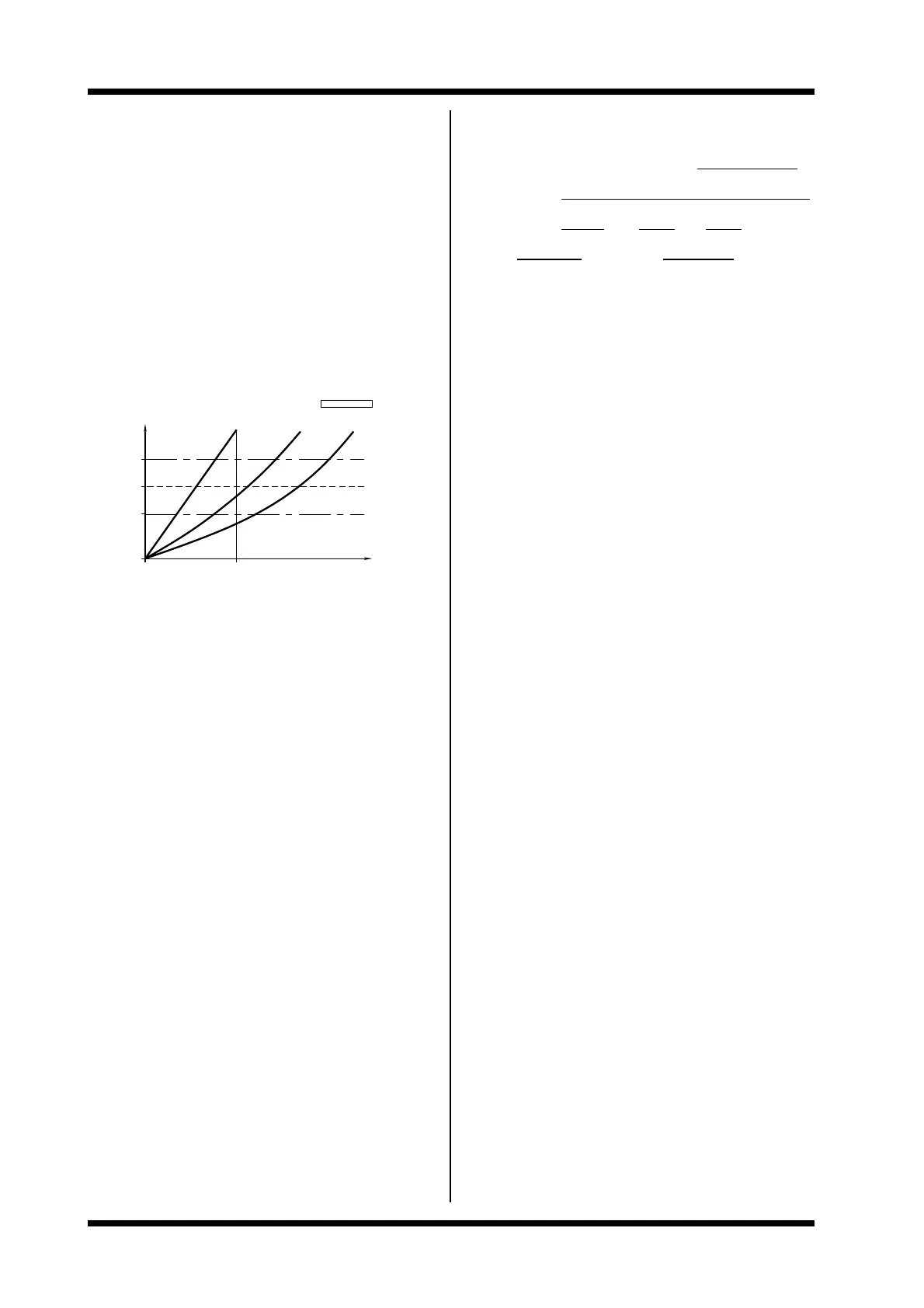
EXAMPLE OF OPERATION OF CONSTANT PRESSURE PUMP
EXAMPLE: OPERATION OF CONSTANT
POINT
LEVEL
HYSTERESIS
LOWER
PRESSURE
(PRESSURE)
SET
LEVEL
HYSTERESIS
UPPER
P
4807−248 Rev B
High flow
SMin
PRESSURE PUMP
No flow
Low flow
(PUMP SPEED)
S
The corresponding process parameters of the Microdrive
setup are:
Setpoint pressure = reference frequency level
Upper - lower pressure limit = feedback sense hysteresis
(54 FB RLY)
Minimum speed (25 Hz) = minimum output frequency
Fmin
(21 MIN FR)
The example given is of a system of the following specification:
Control signal 010V (potentiometer)
Pressure sensor 420mA, 100psi,
12V supply, 3 wire
Motor 132 kW, 245A, 380V,
1485 rpm
Microdrive model 250
Stop/Start Control 2 wire
Direction control reverse inhibited
The configuration table (not including irrelevant and/or settings
which have not been altered from factory set values) and
wiring configurations follow.
CONSTANT PRESSURE PUMPING EXAMPLE
CONFIGURATION TABLE
DRIVE NO: _________ MODEL:____UDi-250____
SITUATION: Constant Pressure Pump - Auto Stop/Start_
MOTOR kW: _132__ A:_245_ V:_380_
POLES:____4____ RPM:__1485____
ADJUSTMENTS
Adjustment 10 MTR CUR
(Default) (= I Inv.)
Setting 245A
Notes Motor nameplate value.
Adjustment 11 MTR VOLT
(Default) (= 415V)
Setting 380
Notes Motor nameplate value.
Adjustment 15 ACC1
(Default) (= 10.0Hz/s)
Setting 5.0
Notes Slower to limit current required to accelerate.
Adjustment 16 DEC1
(Default) (= 10.0Hz/s)
Setting 3.0
Notes Slower to limit current required to decelerate
pump and to prevent regeneration (VLT).
Adjustment 17 T CONST
(Default) (= 0.05s)
Setting 0.1
Notes Value set by experiment - increasing value
improves stability but slows response. Adjust
to achieve good response without instability.
Adjustment 21 MIN FR
(Default) (= 0.0Hz)
Setting 25.0
Notes Sets minimum output frequency.
Adjustment 22 MAX FR
(Default) (= 60Hz)
Setting 50.0
Notes Reduced to 50Hz to avoid overspeed/overload
of pump/motor.
Adjustment 23 FR F1
(Default) (= +0.0Hz)
Setting 0.0
Notes In feedback applications FR F1 should generally
be set equal to the minimum frequency, MIN FR.
Adjustment 24 FR F2
(Default) (= +60.0Hz)
Setting 50.0
Notes In feedback applications FR F2 should generally
be set to equal the maximum frequency, MAX
FR.
 Loading...