Microdrive Series Instruction Manual
4201-109 Rev I
101
ADJUSTMENTS
Adjustment 10 MTR CUR
(Default) (= I Inv.)
Setting 245A
Notes Motor nameplate value.
Adjustment 11 MTR VOLT
(Default) (=415V)
Setting 380
Notes Motor nameplate value.
Adjustment 15 ACC1
(Default) (=10.0Hz/s)
Setting 5.0
Notes Slower to limit current required to accelerate
pump.
Adjustment 16 DEC1
(Default) (=10.0Hz/s)
Setting 3.0
Notes Slower to limit current required to decelerate
pump and to prevent regeneration (VLT).
Adjustment 17 T CONST
(Default) (= 0.05s)
Setting 0.1
Notes Value set by experiment - increasing value
improves stability but slows response. Adjust
to achieve good response without instability.
Adjustment 21 MIN FR
(Default) (= 0.0Hz)
Setting 0.0
Notes Sets minimum output frequency.
Adjustment 22 MAX FR
(Default) (= 60Hz)
Setting 50.0
Notes Reduced to 50Hz to avoid overspeed/overload
of pump/motor.
Adjustment 23 FR F1
(Default) (= +0.0Hz)
Setting 0.0
Notes In feedback applications FR F1 should generally
be set equal to the minimum frequency, MIN FR.
Adjustment 24 FR F2
(Default) (=+60.0Hz)
Setting 50.0
Notes In feedback applications FR F2 should generally
be set equal to the maximum frequency, MAX
FR.
Adjustment 25 MIN FLUX
(Default) (=100%)
Setting 100
Notes If MIN FLUX is set below 100% and the reference
input equals the feedback input, then the motor
voltage will be reduced to improve motor
efficiency. However, this can cause surging
of the motor voltage if the reference or
feedback signals are varying. To avoid surging,
increase MIN FLUX to 100%.
Adjustment 42 DEC3
(Default) (=10.0Hz/s)
Setting 5.0
Notes Slower to limit current required to decelerate
pump and to prevent regeneration (VLT).
MODES
Mode 64 REF FR
(Default) (= 010V)
Setting 010V
Notes 010V is the reference input.
Mode 65 FB SRC
(Default) (=O/LOOP)
Setting 420mA
Notes Connects the 420mA input as the feedback
source.
Mode 66 I/P MODE
(Default) (= 01)
Setting 022 WIRE
Notes Sets the multi-function inputs up for two wire
control.
Mode 71 REV INHIBIT
(Default) (=N)
Setting Y
Notes Inhibits operation in the reverse direction should
this ever inadvertently be demanded.
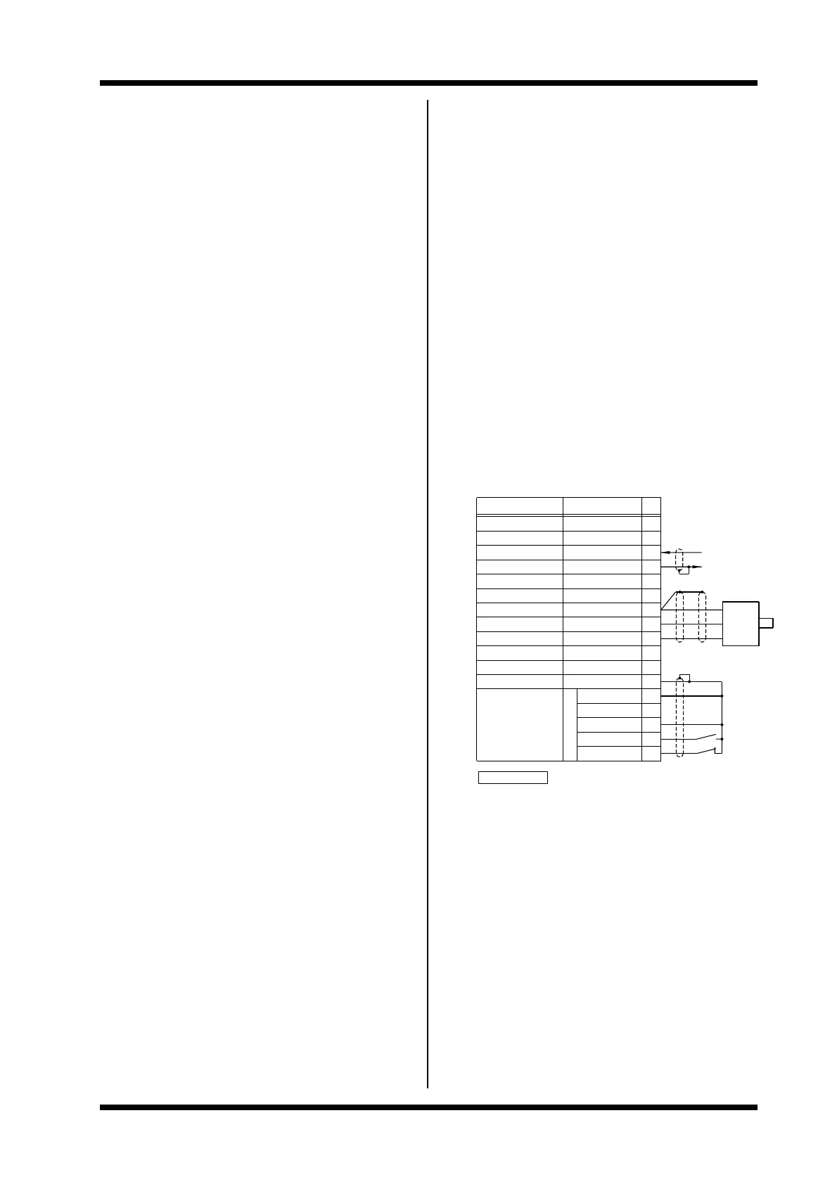
1000PPR
14MOTOR PTCMOTOR PTC
MODE = 1
4807−076 Rev E
SWITCH INPUT 2
SWITCH INPUT 1
0V
SWITCH INPUT 5
SWITCH INPUT 4
SWITCH INPUT 3
START
STOP
8
9
EMERGENCY STOP
DIRECTION INVERT
STOP/RESET
0V
12
11
10
13
EXAMPLE: TACHO CONTROL
WIRING CONFIGURATION
+10V POTENTIOMETER
0V
TACHO INPUT
TACHO SUPPLY
0V
FREQUENCY OUTPUT
FREQUENCY INPUT
0V
FREQUENCY INPUT
0−10V ANALOGUE O/P
I/O NAME
PDL ENCODER 0300−EN
19
SUPPLY
TACHO INPUT
+12V/50mA MAX
0V
0V
15
16
18
17
0V/−mA
0−10V
+ 4−20mA
F = 26.25 F
21
20
O/P
22
23
+V
0V
A
SOURCE
0−10V=0−100Hz
FUNCTION
24
4−20mA