Microdrive Series Instruction Manual
4201-109 Rev I
62
43 PULSE TACHO GAIN
Screen 43 T GAIN =20.0
Description PULSE TACHO INPUT SCALING FACTOR
Min/Max 1.0/999
Units OP Hz/IP kHz
Notes Measured in terms of output Hz per input
(tacho) kHz.
FUNCTION Used, in association with tacho control modes,
to match the encoder (pulse tacho) frequency
to the required Microdrive output frequency.
In the feedback mode (feedback source set to
TACHO - Screen 65) tacho gain is used to
match the encoder feedback frequency to the
Microdrive output frequency. The long term
speed accuracy obtained is better then 99.99%
(<0.01% error ).
In the follower mode (reference frequency
source set to TACHO - Screen 64) tacho gain
is used to match the Microdrive output
frequency to a master process.
SETTING UP This setting has no effect unless a tacho mode
is selected.
Tacho Feedback:
Ascertain the expected encoder frequency
(kHz) at a given Microdrive output frequency
(typically 50Hz). Calculate the required tacho
gain by dividing the Microdrive output frequency
(in Hz) by the encoder frequency (kHz). Enter
this gain.
Tacho Follow:
Ascertain the expected encoder frequency
(kHz) at a given speed of the master process.
Calculate the required tacho gain by dividing
the required Microdrive output frequency (in
Hz) by the encoder frequency (kHz). Enter this
gain.
If you find that your calculated tacho gain is
outside the adjustment range (1.0 to 999 output
Hz per input kHz), you will have to alter your
encoder gearing or choose an encoder with a
different number of pulses per revolution.
Notes: As the tacho is sampled over a 100ms period,
very low pulse rates can give rise to quantisation
errors in the tacho follow mode.
43
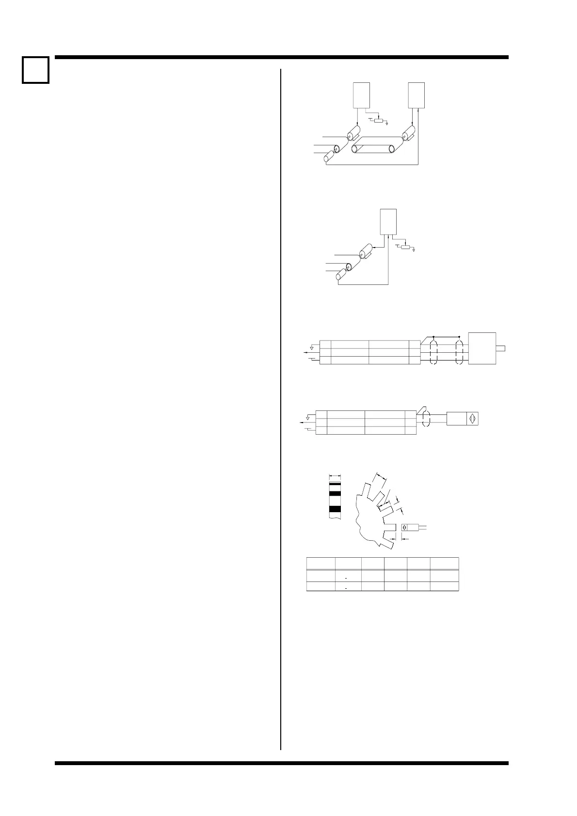
MICRODRIVEMICRODRIVE
ENCODER
SET SPEED
+10V
TYPICAL EXAMPLE OF TACHO FOLLOW APPLICATION
-CONVEYOR SPEED FOLLOWING
MICRODRIVE
ENCODER
SET SPEED
+10V
TYPICAL TACHO FEEDBACK APPLICATION
-PRECISION SPEED REGULATION
FOLLOWERMASTER
+12V
18
17
16 16
17
18
TACHO SUPPLY
TACHO INPUT
0V
+12V/50mA MAX
TACHO INPUT
0V
0V
TACHO INPUT
+12V/50mA MAX
0V
TACHO INPUT
TACHO SUPPLY
18
17
1616
17
18
+12V
Bi-2-G12-Y0 15mm MIN. 6mm MIN. 6mm MIN. 12mm MIN.0.8 +0.4mm
0.4 +0.2mm
LENGTH
8mm MIN.4mm MIN.4mm MIN.10mm MIN.Bi-1-G08-Y0
MODEL
GAP
DEPTH
TOOTH
LENGTH
TOOTH
WIDTHGAP
SENSOR
GAP
SENSOR
PROXIMITY
TOOTH DEPTH
GAP LENGTH
TOOTH LENGTH
TOOTH WIDTH
4807-070 Rev F
PROXIMITY SENSOR
PDL ENCODER 0300 EN
1000PPR
BROWN
BLUE
+V
A
0V
 Loading...