Microdrive Series Instruction Manual
4201-109 Rev I
103
Adjustment 25 MIN FLUX
(Default) (=100%)
Setting 100
Notes If MIN FLUX is set below 100% and the reference
input equals the feedback input, then the motor
voltage will be reduced to improve motor
efficiency. However, this can cause surging
of the motor voltage if the reference or feedback
signals are varying. To avoid surging, increase
MIN FLUX to 100%.
Adjustment 42 DEC3
(Default) (=10.0Hz/s)
Setting 2.0
Notes Slower to limit current required to decelerate
pump and to prevent regeneration (VLT).
Adjustment 54 FB RLY
(Default) (= 10.0Hz)
Setting 5.0
Notes Hysteresis band around the reference
frequency outside which the feedback sense
relay changes state.
MODES
Mode 64 REF FR
(Default) (= 010V)
Setting 010V
Notes 010V is the reference input.
Mode 65 FB SRC
(Default) (= 0/LOOP)
Setting 420mA
Notes Connects the 420mA input as the feedback
source.
Mode 66 I/P MODE
(Default) (= 01)
Setting 022 WIRE
Notes Sets the multi-function inputs up for two wire
control.
Mode 68 O/P RELAY 2
(Default) (= 00 NO FAULT)
Setting 13 FEEDBACK SENSE
Notes Sets relay 2 to open when the feedback signal
is higher than the reference plus half the
hysteresis.
Mode 71 REV INHIBIT
(Default) (= N)
Setting Y
Notes Inhibits operation in the reverse direction should
this ever inadvertently be demanded.
Mode 78 RUN AT MINIMUM FREQUENCY
(Default) (= N)
Setting Y
Notes Allows the drive to run at the minimum frequency
(Screen 21) causing the pressure rise
necessary to reach the upper hysteresis level.
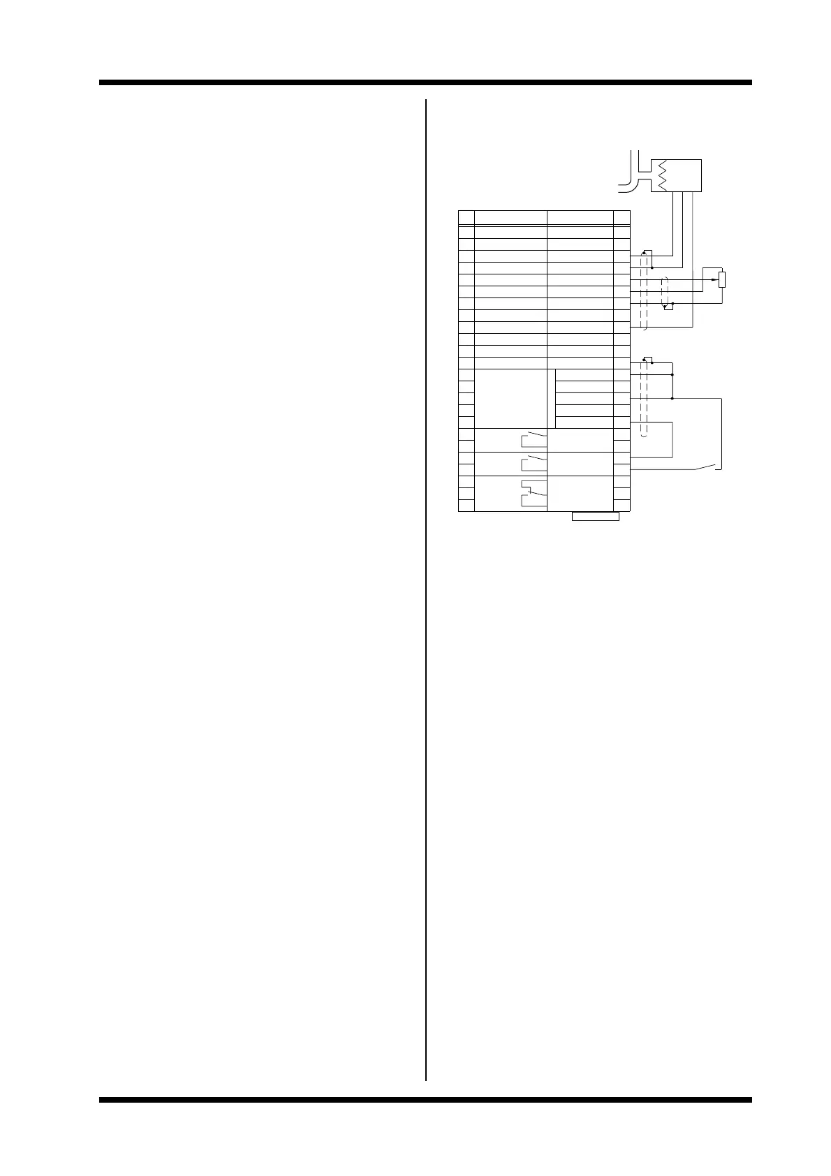
FEEDBACK
EMERGENCY STOP
START/STOP
SERIAL COMMS.
STOP/RESET
DIRECTION INVERT
MOTOR PTC
7
OUTPUT
RELAY 3
RELAY 2
OUTPUT
RELAY 1
OUTPUT
3
2
1
6
5
4
SWITCH INPUT 5
SWITCH INPUT 1
SWITCH INPUT 2
SWITCH INPUT 3
SWITCH INPUT 4
MOTOR PTC
11
8
9
10
12
13
14
MODE = 2
0V
7
3
4807−249 Rev E
1
2
SENSE
5
4
6
11
9
8
10
0V
12
14
13
+ 4−20mA
0−10V=0−100Hz
F = 26.25 F
FUNCTION
TACHO INPUT
SUPPLY
EXAMPLE: PRESSURE CONTROL WIRING CONFIGURATION
INCLUDING AUTOMATIC STOP/START CONTROL
22
FREQUENCY INPUT
TACHO INPUT
TACHO SUPPLY
+10V POTENTIOMETER
FREQUENCY INPUT
18
15
16
17
19
20
21
0V
0V
0V
I/O NAME
FREQUENCY OUTPUT
0−10V ANALOGUE O/P
23
24
PRESSURE
PRESSURE
22
0V 18
0V
16
15
17
0−10V
0V/−mA
20
19
21
O/P
23
24
SENSOR
SET
 Loading...