Relion 1900e/2900e Manual
95 Revision 1.3
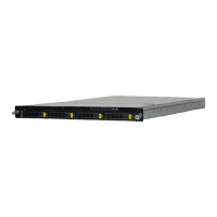
10.2.2 Front Panel LED and Control Button Features Overview
10.2.2.1 Power/Sleep Button and LED Support
Pressing the Power button will toggle the system power on and off. This button also functions as a sleep
button if enabled by an ACPI compliant operating system. Pressing this button will send a signal to the
integrated BMC, which will power on or power off the system. The power LED is a single color and is capable
of supporting different indicator states as defined in the following table.
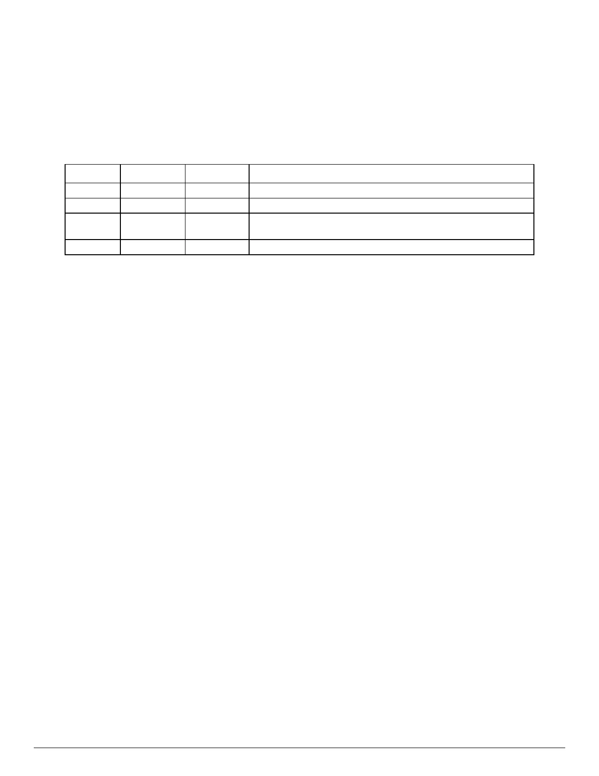
Table 33. Power/Sleep LED Functional States
10.2.2.
2 System ID Button and LED Support
Pressing the System ID Button will toggle both the ID LED on the front panel and the Blue ID LED on the back
edge of the server board, on and off. The System ID LED is used to identify the system for maintenance when
installed in a rack of similar server systems. The System ID LED can also be toggled on and off remotely
using the IPMI “Chassis Identify” command which will cause the LED to blink for 15 seconds.
10.2.2.
3 System Reset Button Support
When pressed, this button will reboot and re-initialize the system
10.2.2.4 NMI Button Support
When the NMI button is pressed, it puts the server in a halt state and causes the BMC to issue a non-
maskable interrupt (NMI) for generating diagnostic traces and core dumps from the operating system. Once
an NMI has been generated by the BMC, the BMC does not generate another NMI until the system has been
reset or powered down.
The following actions cause the BMC to generate an NMI pulse:
Receiving a Chassis Control command to pulse the diagnostic interrupt. This command does not
cause an event to be logged in the SEL.
Watchdog timer pre-timeout expiration with NMI/diagnostic interrupt pre-timeout action enabled.
State Power Mode LED Description
System power is off, and the BIOS has not initialized the chipset.
S5 ACPI Off
Mechanical is off, and the operating system has not saved any
context to the hard disk.
System and the operating system are up and running.