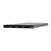
Relion 1900e/2900e Manual
Revision 1.0 32
5. System I/O
The server board Input/Output features are provided via the embedded features and functions of several
onboard components including: the Integrated I/O Module (IIO) of the Intel
®
Xeon
®
E5-2600 v3, v4 processor
family, the Intel
®
C612 chipset, the Intel
®
Ethernet controller I350 or X540, and the I/O controllers embedded
within the Emulex* Pilot-III Management Controller.
See Figure 6. Relion 1900e/2900e Architectural Block Diagram for an overview of the features
and interconnects of each of the major sub-system components
5.1 PCIe* Support
The processor side PCI Express interface of S2600 server boards is fully compliant with the PCI Express Base
Specification, Revision 3.0. It provides support for PCI Express Gen 3 (8.0 GT/s), Gen 2 (5.0 GT/s), and Gen
1(2.5 GT/s).
The Integrated I/O (IIO) module of the Intel
®
Xeon
®
Processor E5-2600 v3, v4 product family provides the PCI
express* interface for general purpose PCI express* devices at up to PCI express* 3.0 speeds.
The
IIO module provides the following PCIe* Features:
Compliant with the PCI express* Base Specification, Revision 2.0 and Revision 3.0
2.5 GHz (Gen1) and 5 GHz (Gen2) and 8 GHz (Gen3)
x16 PCI-Express 3.0 interface supports up to four x4 controllers and is configurable to 4x4 links, 2x8,
2x4\1x8, or 1x16
x8 PCI-Express 3.0 interface supports up to 2 x4 controllers and is configurable to 2x4 or 1x8
Full peer-to-peer support between PCI express* interfaces
Full support for software-initiated PCI express* power management
x8 Server I/O Module support
TLP Processing Hints (TPH) for data push to cache
Address Translation Services (ATS 1.0)
PCIe* Atomic Operations Completer Capability
Autonomous Linkwidth
x4 DMI2 interface
• All processors support a x4 DMI2 lane which can be connected to a PCH, or operate as a x4
PCIe* 2.0 port.
The
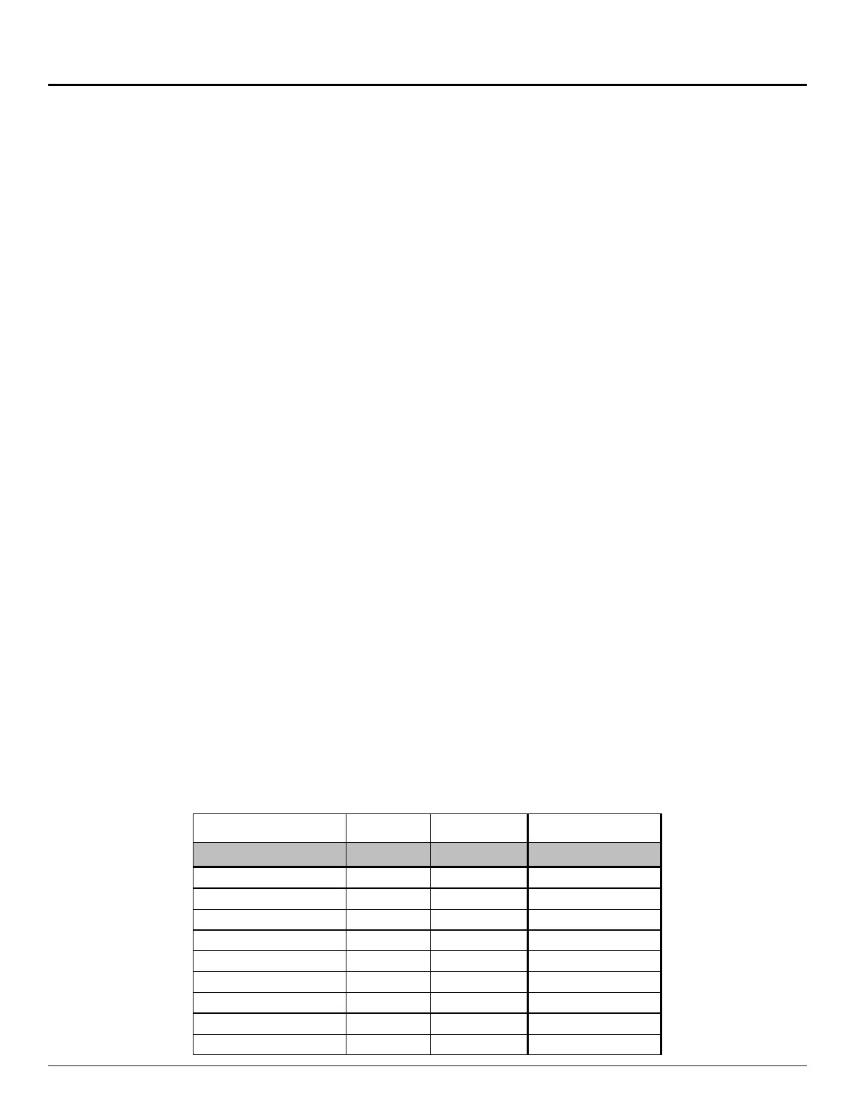
following tables provide the PCIe* port routing information:
Table 7. PCIe* Port Routing CPU #1