Revision 1.0 96
Relion 1900e/2900e Manual
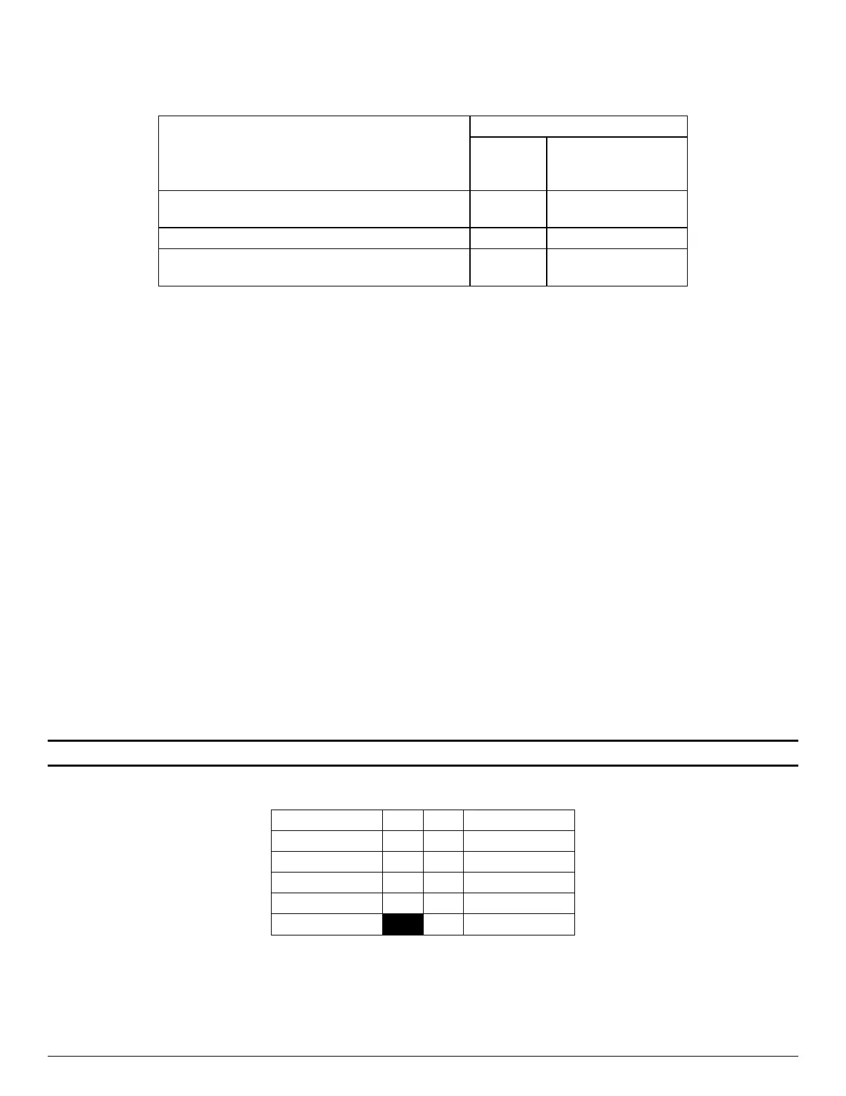
The following table describes behavior regarding NMI signal generation and event logging by the BMC.
Table 34. NMI Signal Generation and Event Logging
Causal Event
Generation
Interrupt Sensor Event
Logging Support
Chassis Control command (pulse diagnostic
interrupt)
X –
Front panel diagnostic interrupt button pressed
Watchdog Timer pre-timeout expiration with
NMI/diagnostic interrupt action
X X
10.2.2.5 NIC Activity LED Support
The Front Control Panel includes an activity LED indicator for each on-board Network Interface Controller
(NIC). When a network link is detected, the LED will turn on solid. The LED will blink once network activity
occurs at a rate that is consistent with the amount of network activity that is occurring.
10.2.2.6 Storage Device Activity LED Support
The storage device activity LED on the front panel indicates drive activity from the on-board storage
controllers. The server board also provides a 2-pin header, labeled “HDD_Activity” on the server board,
giving access to this LED for add-in controllers.
10.2.2.7 System Status LED Support
The System Status LED is a bi-color (Green/Amber) indicator that shows the current health of the server
system. The system provides two locations for this feature; one is located on the Front Control Panel, the
other is located on the back edge of the server board, viewable from the back of the system. Both LEDs are
tied together and will show the same state. The System Status LED states are driven by the on-board
platform management sub-system. See section 12.2 for a list of supported System Status LED states.
10.2.3 Front Panel USB 2.0 Connector
The server board includes a 10-pin connector that, when cabled, can provide up to two USB 2.0 ports to a
front panel. On the server board the connector is labeled “FP_USB_2.0_5-6” and is located on the left side
of the server board near the I/O module connector. The following table provides the connector pin-out.
Note: The numbers 5 & 6 in the silk screen label identify the USB ports routed to this connector.
Table 35. Front Panel USB 2.0 Connector Pin-out ("FP_USB_2.0_5-6 ")