Relion 1900e/2900e Manual
75 Revision 1.3
6. On-board sensor
7. Virtual sensor
8. Available only when PSU has PMBus
9. Calculated estimate
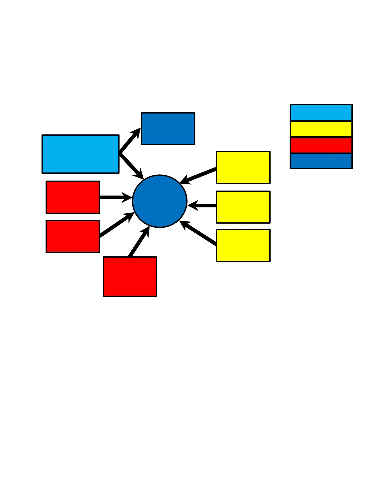
A sim
ple model is shown in the following figure which gives a high level representation of how the fan speed
control structure creates the resulting fan speeds.
Figure 26. High-level Fan Speed Control Process
7.3.14.6.1 Processor Thermal Management
Processor thermal management utilizes clamp algorithms for which the Processor DTS-Spec margin sensor
is a controlling input. This replaces the use of the (legacy) raw DTS sensor reading that was utilized on
previous generation platforms. The legacy DTS sensor is retained only for monitoring purposes and is not
used as an input to the fan speed control.
7.3.14.6.2 Memory Thermal Management
The system memory is the most complex subsystem to thermally manage, as it requires substantial
interactions between the BMC, BIOS, and the embedded memory controller HW. This section provides an
overview of this management capability from a BMC perspective.
7.3.14.6.2.1 Memory Thermal Throttling
The system only supports thermal management through closed loop thermal throttling (CLTT) on system
that installed with DDR4 memory with temperature sensors. Throttling levels are changed dynamically to cap
throttling based on memory and system thermal conditions as determined by the system and DIMM power
and thermal parameters. Support for CLTT on mixed-mode DIMM populations (that is, some installed DIMMs
Speed
Throttle
Settings
Other Sensors
(Chipset, Temp,
etc..)
Policy: CLTT,
Acoustic/Performance,
Auto-Profile