A200SP Absorber 8 User Manual
Description
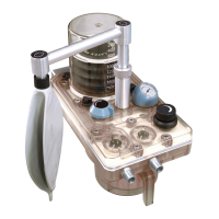
3.4 Adjustable Pressure Limiting (APL) Valve
The APL valve (1) s a sprng loaded plastc float wth a rubber
seal, provdng breathng system pressure control, and excess
pressure relef
The sprng pressure can be vared by rotatng the control
knob on top of the valve In the fully counterclockwse poston
the mnmum pressure s 10 cmHO at 6 L/mn Ths can be
ncreased by clockwse rotaton to 60 cmHO
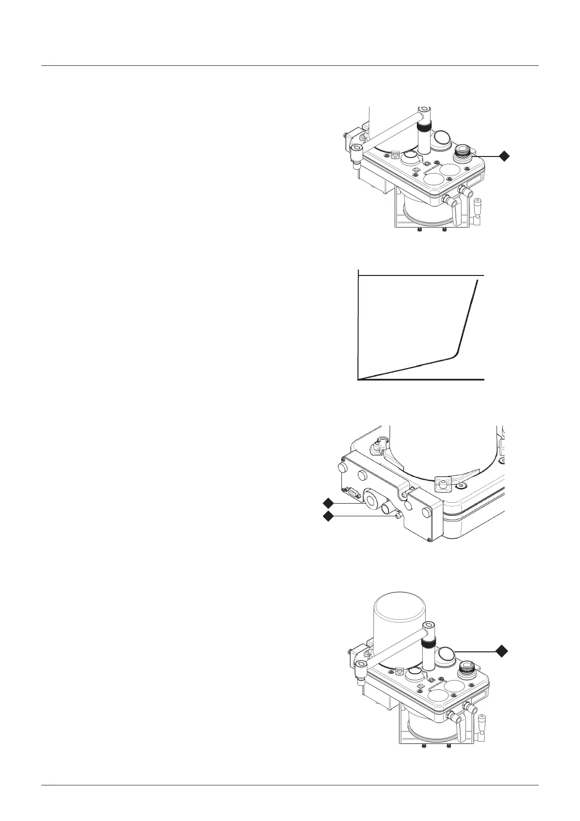
As shown n the graph, further clockwse rotaton causes a
rapd ncrease n openng pressure so that n the fully closed
poston, the valve functons as a 60 cmHO excess pressure
relef valve
WARNIN
The APL valve (1) s out of crcut when the system s n
‘Ventlator’ mode The ventlator must be equpped wth a
pressure relef valve
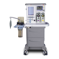
3.5 AGSS Outlet and Fresh Gas Inlet and
Hose
ASS (anaesthetc gas scavengng system) connector
Taper connector (1) at rear of absorber assembly
Fresh as Inlet and Hose
The fresh gas nlet (2) s at the rear of the absorber
The absorber s suppled wth a fresh gas hose assembly wth
an attached end fttng Do not use any other type of hose
WARNIN
Knkng of the fresh gas hose s a known cause of
anaesthetc accdent The use of an unsutable hose
assembly can contrbute to ths stuaton
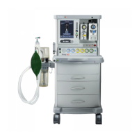
3.6 Manometer
The use of a manometer s strongly recommended at all tmes
The manometer (1) s located on the top of the manfold block
Manometer scale -10 to +100 cmHO
Manometer accuracy ±5% (wthn range +10 to 80 cmHO)
AUTION
Remove the manometer before autoclavng the absorber
manfold block - see secton 85
1
Open losed
lockwse rotaton
60
Pressure
(cmHO)
1
2
1