A200SP Absorber 11 User Manual
Description
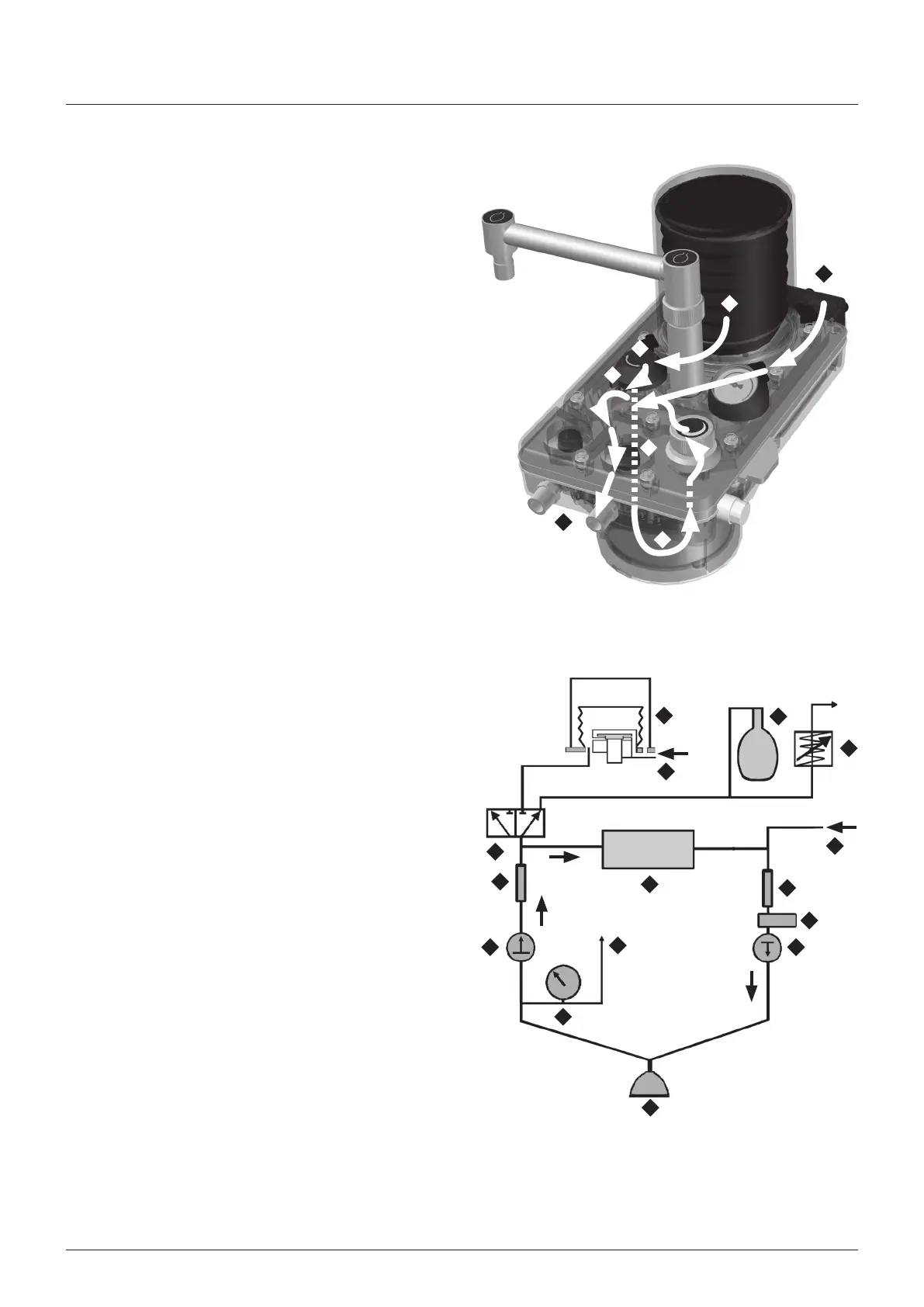
3.11 Gas Flow
Inspratory as Path
A Patent as from bellows
B Through the bag/ventlator swtch
Down to absorbent canster
D Through the absorbent
E Fresh gas flow from anaesthetc machne
F Into the nspratory non-return valve
Through nspratory connector to patent breathng crcut
as Flow Schematc
NOTE
The schematc represents the gas path wth the absorber ‘ON’
(e the absorbent canster n the ‘locked-on’ poston, see
secton 313)
1 Ventlator bellows
2 Bag/ventlator swtch
3 Absorbent canster
4 Fresh gas flow from anaesthetc machne
5 Inspratory non-return valve
6 Adustable pressure lmtng valve (APL) valve
7 Breathng bag
8 Patent
9 Expratory non-return valve
10 Manometer
11 Pressure montor sample lne
12 Ventlator drve gas
13 Oxygen montor sensor
14 Sprometer flow sensors
E
G
D
F
C
B
A
1
12
7
3
6
14
2
9
10
11
8
5
13
14
4