A200SP Absorber 18 User Manual
Installation and Operation
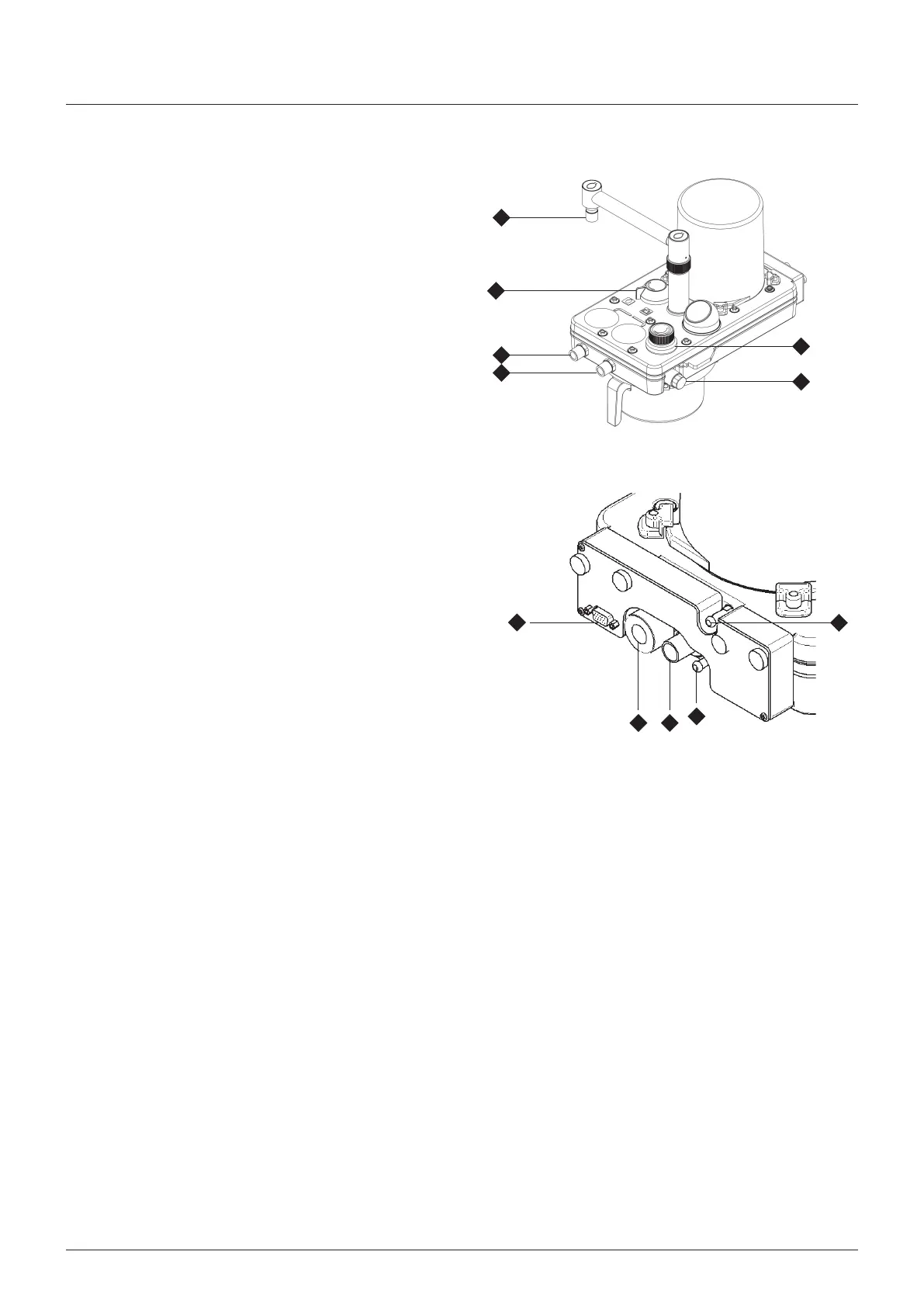
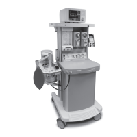
5.2.1 Breathing System
1 Inspratory (1) and expratory (2) hose connectors and the
reservor bag connector (3) are 22 mm male, complyng wth
BS EN ISO 5356/1
2 Use a heat and mosture exchanger (HME) at the patent
Y-pece
AUTION
Replacement/Dsposal - always follow the nstructons
suppled wth the flter or HME
Ft new components at the recommended nterval
3 The bag arm s heght adustable, and the bag connector can
be rotated to the desred poston
4 Ventlator-to-bellows connecton pont (4) onnect a 17 mm
dameter corrugated hose between the ventlator control unt
drve gas outlet (labelled DRIVE AS) and the connector (4)
at the rear of the absorber
5.2.2 Fresh Gas Supply
onnect the fresh gas hose from the common gas outlet of the
anaesthetc machne assembly to the connector (5)
5.2.3 Anaesthetic Gas Scavenging (AGS)
The outlet (6) from the adustable pressure lmtng (APL) valve (7)
must be connected to a recever system
WARNIN
Do not connect a vacuum system drectly to the APL valve
outlet
A recevng system wth a postve and negatve pressure
control functon must be nterposed The recevng system
must comply wth the requrements of EN ISO 8835 part 2
5.2.4 Oxygen Monitor
The use of an oxygen montor (and a carbon doxde analyser)
s hghly recommended when usng any partal rebreathng
anaesthetc system
The oxygen sensor (8) s ftted to the rght hand sde of the
absorber
Bacteral Flter
Use a breathng system bacteral flter n the expratory lmb of the
breathng crcut to protect the oxygen sensor (see secton 5 n the
ventlator user manual)
AUTION
Replacement/Dsposal - always follow the nstructons suppled
wth the flter, and always replace at the recommended nterval
5.2.5 Pressure Monitor
Pressure montor self-sealng connector (9)
onnect to PATIENT PRESSURE port on the rear panel of the
ventlator control unt
3
11
2
1
8
7
10
5
9
46