A200SP Absorber 17 User Manual
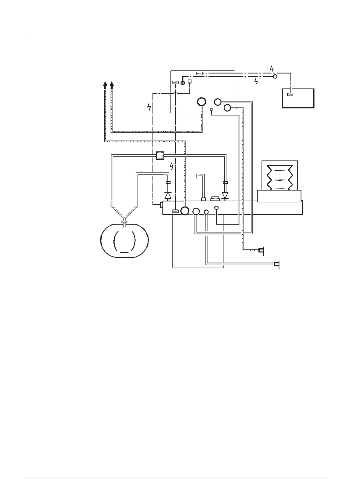
Hoses and cables schematc
showng the absorber
connected to a ventlator
control unt wth remote
screen
NOTE
1 Ventlator has sprometry
and oxygen montor
functons
2 Interface cablng s
shown for connecton to
the anaesthetc machne
on/off swtch and
absorber bag/ventlator
swtch
23
22
23
21 24
29
28
18
19
2
12
17
4
7
6
11
14
27
26
16
12
15
25
10
13
5
1
3
20
9
8
Installation and Operation
1 Ventlator bellows
2 Ventlator control unt
3 Outlets to anaesthetc gas scavengng system (ASS)
4 Bacteral flter
5 Absorber valve block
6 Heat and mosture exchanger (note that a combned unt
wth a bacteral flter can be used - see 521)
7 Patent
8 ommon gas outlet on anaesthetc machne (fresh gas
supply)
9 Auxlary outlet on anaesthetc machne (ventlator drve
gas supply)
10 Flow sensor - expratory
11 Flow sensor - nspratory
12 onnectors - sensor - patent pressure montor
13 Expratory valve - absorber
14 Inspratory valve - absorber
15 onnector - reservor bag
16 Inlet - absorber - fresh gas supply
17 Drve gas nlet - ventlator
18 Drve gas outlet - ventlator control unt to bellows
19 Outlet - ventlator exhaust valve
20 Inlet - bellows drve gas (routed through the absorber)
21 Input socket - oxygen montor sensor
22 Input socket - ventlator (anaesthetc machne nterface -
on/off swtch)
23 Interface connecton, absorber to ventlator
a) Absorber bag/ventlator control poston
b) Sprometer sensor sgnal
24 Interface output connecton on anaesthetc machne
25 Adustable pressure lmtng (APL) valve
26 Outlet from APL valve to ASS
27 Oxygen sensor
28 Remote screen unt
29 Output sgnal connector - ventlator control unt to remote
screen