A200SP Absorber 9 User Manual
Description
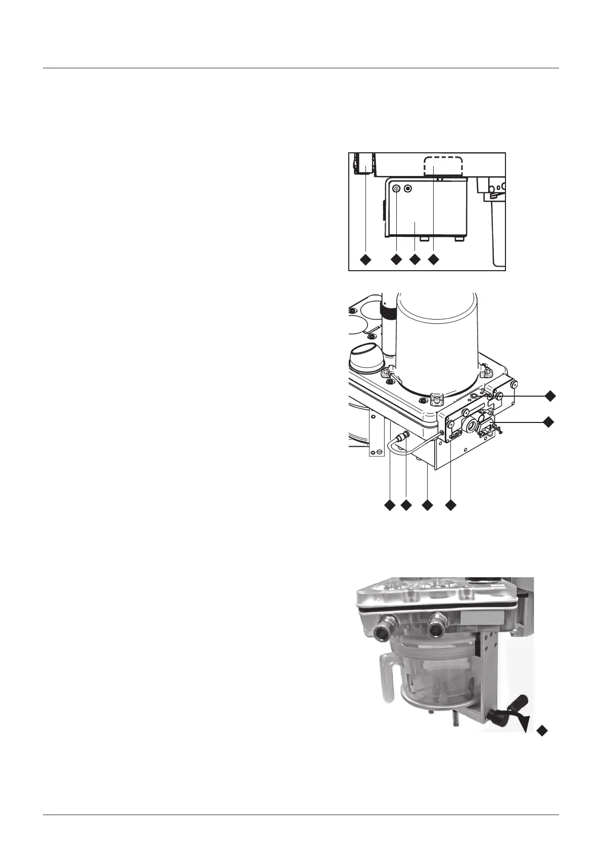
3.7 Heater Unit (option)
NOTE
Interrupton of the heater unt mans power supply wll result n
the heater unt not functonng
When the Mans power plug s removed from the heater unt power
socket (4)
• Power to the heater unt (2) s nterrupted
• The heater unt (2) s solated from the mans supply
The heater unt (2) and the auxlary heater element (5) each
have a sngle power ndcator lamp The power ndcator lamp s
llumnated when mans power s appled to the assembly
3.7.1 Absorber Gas Path Heater
The heater elements are mounted wthn the support blocks (1)
mounted at each sde of the top of the heater control unt (2) The
elements heat the base of the absorber and lmt the buld up of
mosture n the gas paths
The heater operates automatcally, When the heater s powered,
usng the socket (4), a power ndcator lamp (3) on the sde of the
unt s llumnated
AUTION
Do not autoclave the heater unt or heater elements
3.7.2 Spirometer Sensor Heater
The sprometer sensors are mounted nsde the electrcal nterface
unt (5) and each sensor s heated by an ndvdual heater element
to lmt the buld up of mosture and mantan sensor performance
The heater elements operate automatcally, a power ndcator
lamp (6) s llumnated, when the cable (7) s connected to the
socket (8) on the heater control unt
AUTION
Do not autoclave the electrcal nterface unt
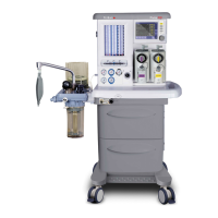
3.8 Bypass System
The absorber reverts to bypass mode when the canster release
lever s turned clockwse to the unlocked poston (1)
Expratory gas cycles to the patent, wthout passng through the
absorbent
It s strongly recommended that a capnometer s used to prevent
the rsk of hypercapna
3.9 End Tidal Carbon Dioxide Monitoring
The use of end tdal carbon doxde (EtO) montorng s strongly
recommended
onnecton of a sutable analyser must be made between the
patent’s arway and the patent connecton Y-pece
Read the nstructons provded by the manufacturer of the
analyser
5
3 12
8
6
7 2 5
4
1