5
EasyTouch Control System User’s Guide
Controls and buttons (Continued)
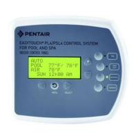
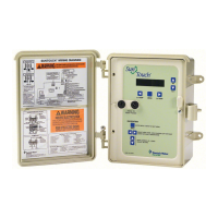
Valves (V) - (Pool/Spa/Fill (Spillway)/Drain) button: When in normal operating mode, the
Val ves ( V) b utto n is i n “P o ol” m od e . In t his m od e the v alv es a r e au toma tic ally r ot a ted s o th at
only the pool water is circulated through the system and the filter pump is activated. Pressing this
button once enables “Spa” mode and activates the filter pump to circulate only spa water
through the system. “Fill/Spillway” and “Drain” mode can only be used while in “Service” mode
(See Mode button for details). “Fill/Spillway” and “Drain” mode are used when cleaning the spa.
Pressing the Valves (V) button again returns the system to “Pool” mode. Note that the filter
pump will switch off while the pool/spa valves are rotating into position. The current operating
mode is shown in the LCD display. Note: The Valves button (Pool, Spa, Fill (Spillway),
Drain) button has no function in “Pool only” or “Spa only” systems. For an EasyTouch
single body system, “Pool” and “Spa” modes are Lo- Temp (Pool) and Hi-Temp (Spa)
temperature controls. For more information, see “Hi-Temp/Lo-Temp Controls for Single
Body Systems,” page 41.
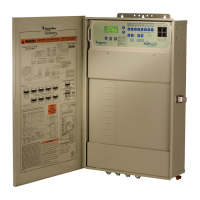
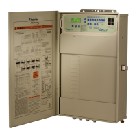
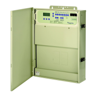
Aux 1 - 7 buttons/LEDs: Auxiliary output circuit buttons operate the pool and spa system valves,
lights and other equipment. These auxiliary circuits are assigned in the “Circuit Function” menu, see
page 39 for details. There are three auxiliary circuits (AUX 1- 3) on the EasyTouch 4 outdoor
control panel and seven auxiliary circuits (AUX 1- 7) on EasyTouch 8 outdoor control panel. The
Solar button can also be used for an “extra” auxiliary circuit if the Solar circuit is not being for solar
equipment. Labels can be affixed next to each auxiliary button to identify the circuit function. Labels
can be affixed over each auxiliary button to identify the circuit function. When an auxiliary circuit is
activated or the button is pressed, the LED is on. Pressing an auxiliary circuit button will activate the
corresponding circuit in either “Auto” or “Service” mode. When a circuit relay is switched on
manually, it remains on until either you switch it off manually, or the next time the relay is scheduled
to be switched off. For example, if the filter pump is scheduled to automatically run from 9:00 AM to
5:00 PM daily then the filter pump is switched on manually at 9:00 PM, it will run continuously until
the next day at 6:00 PM then switch off. The schedule will then continue from then on.
Heater (Flame) button/LED: This button is only used in “Service” mode for manual heat on and off
control. The Heater LED will be on if “Heater” is enabled in the “Heat” menu setting (see page 25).
Switching the heater on automatically controls the output between a “forced off” state and a normal
automatic thermostatic control operating state. The heater will continue heating the water until the
heater’s current highest set point temperature triggers the heater sensor (approximately 104° F).
Note that the Heater button does not activate the pump. Do not activate the heater without running
the pump. The heater will not run if water flow is not detected.
Solar (Sun) button/LED and (Aux Extra): In solar mode this button is only used in “Service” mode
for manual solar heat on and off control. The Solar LED will be on if “Solar” is enabled in the
“Heat” menu setting. Solar must also be enabled in the “Solar” menu. Use the Solar button to
manually switch the heater control output between a “forced off” state and a normal automatic
thermostatic control operating state. When this button is pressed the solar relay is switched on to
activate a booster pump if installed and activates valves to rotate to divert water through solar
heating panels. If solar equipment is not being used, this button can also be used to switch the AUX
EXTRA circuit on and off.
Reset button: Press this button to reinitialize the EasyTouch outdoor control panel.
IntelliChlor circuit breaker (SCG system only): The circuit breaker opens in case the circuit is
shorted or overloaded. Press circuit breaker to reset power to the IntelliChlor.
Low voltage circuit breakers: Three amp circuit breakers protect the low voltage system
motherboard circuits, relays and valves.
T
U
V
 Loading...
