AS-Interface
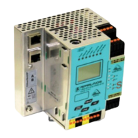
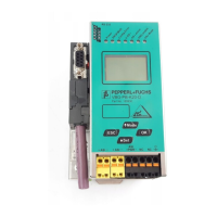
Connections, Displays and Operating Keys
Subject to reasonable modifications due to technical advances. Copyright Pepperl+Fuchs, Printed in Germany
Pepperl+Fuchs Group · Tel.: Germany (6 21) 7 76-0 · USA (3 30) 4 25 35 55 · Singapore 7 79 90 91 · Internet http://www.pepperl-fuchs.com
Issue date - 21.12.2005
10
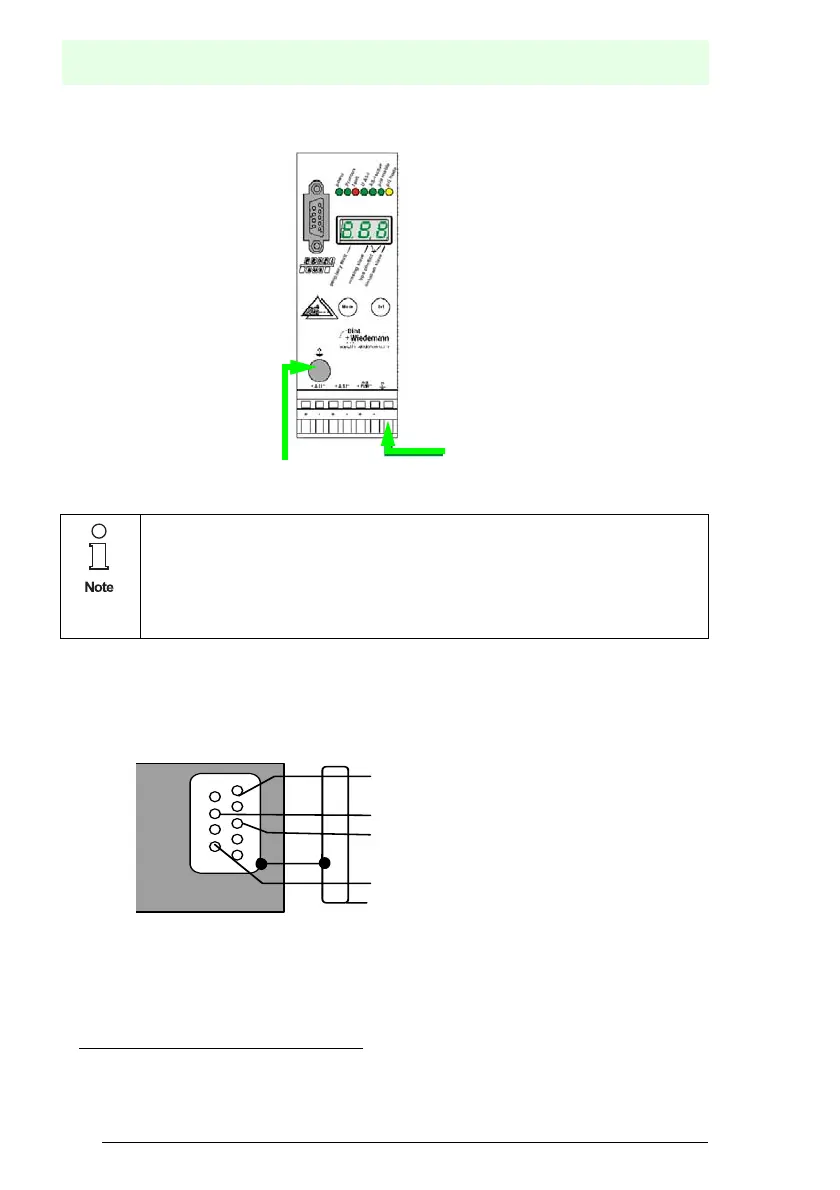
5.1.1.1 Function Ground
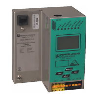
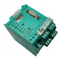
5.2 PROFIBUS Interface
The PROFIBUS interface is realized as a 9-pin SUB-D connector, in accordance
to the standard for PROFIBUS DIN 19245. It is placed at the top left-hand corner
of the master
The AS-i/PROFIBUS gateway sends and receives on pins 3 and 8 of the SUB-D
socket. The PROFIBUS signal “RxD/TxD-N (data line A)
1
” is located on pin 8, the
signal “RxD/TxD-P (data line B)
1
” is located on pin 3.
The pins 5 (0 V) and 6 (5 V) supply 5 V DC for the bus termination.
• The function ground can be connected either at the ground screw or at the
terminal.
• The function ground should be connected with a cable as short as possible to
guarantee a good EMC property.
• Therefore is to prefer to connect the ground via the ground screw.
1. If you measure the DC voltage between RxD/TxD-P (data line B) and RxD/TxD-N (data line A), RxD/TxD-P (data line B) is the positive pole
when the bus is silent.
Function ground
5
4
3
2
1
9
8
7
6
RxD/TxD-P
(data line B)
RxD/TxD-N
(data line A)
PROFIBUS
VP / +5 Volt)
DGND (0 Volt)