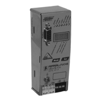
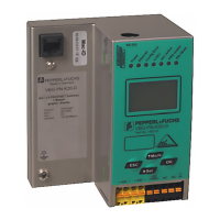
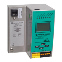
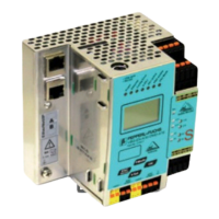
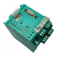
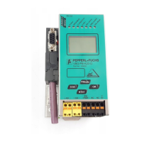
AS-i/PROFIBUS Gateway
PROFIBUS DP
Subject to reasonable modifications due to technical advances. Copyright Pepperl+Fuchs, Printed in Germany
Pepperl+Fuchs Group · Tel.: Germany (6 21) 7 76-0 · USA (3 30) 4 25 35 55 · Singapore 7 79 90 91 · Internet http://www.pepperl-fuchs.com
Issue date - 21.12.2005
21
F: 1: EC-flags will be transmitted in the diagnosis
0: EC-flags will not be transmitted
FD: If this bit is set, the PROFIBUS diagnosis is refreshed only if the PROFIBUS
norm dictates this ("freeze diagnosis"). In doubt the data of the PROFIBUS
masters diagnosis are not up to date.
CS: 1: ExtDiag will be set if the LCS is not empty
0: ExtDiag will not be set if the LCS is not empty
PF: 1: ExtDiag will be set if there is a periphery fault at the AS-i line
0: ExtDiag will not be set.
APF: 1: ExtDiag will be set if there is an AS-i Power Fail
0: ExtDiag will not be set.
CF: 1: ExtDiag will be set if there is a configuration error
0: ExtDiag will not be set.
The GSD's default user parameter telegram is:
(DPV1 enabled, diagnosis settings according to chapter 7.1.1)
7.1.2 Configuration DP V0 (cyclic data)
The configuration of the AS-i/PROFIBUS gateways is made with the GSD file.
Therefore the provided GSD file has to be imported into your PROFIBUS configu
-
ration tool.
7.1.2.1 Options
The original data input and outlet data can be used with different „Spezial IDs“.
The advantages of special input and output IDs are, that they can include up to 64
elements (bytes or words), and that the length of input and output data can be dif
-
ferent. Additionally, "manufacturer specific" data bytes describing the ID type are
possible. These "manuafaturer specific" data bytes describe the which type ID is.
The GSD file offers here several combinations (several lengths) for transmitting I/
O date, command interface (management) and analog data.
Therefore the analog data can be transmitted directly in the process data channel
and do not have to be requested by the slower DP
V1 commands.
Maximally 8 modules can be cofigurated.
80
16
00
16
00
16
0B
16
06
16
00
16