PAL-AT Operating Manual
39
4 Tests and Maintenance
Warning - Before accessing the PAL-AT panel, the panel must be disconnected from the
power source and isolated from any hazardous voltage present in the panel, e.g. relay wiring.
Refer to the PAL-AT Installation Manual for wiring instructions. Refer all servicing to qualified
personnel.
4.1 Select Test Mode
It is recommended to select Test Mode and disable mapping before conducting periodic tests on the cable.
This prevents the system from automatically creating a new map after a leak or drying test (see section
2.9.8). At the end of testing when the cable has returned to normal, enable mapping again.
4.2 Alarm Test
Every six months or more frequently, depending on the application, test PAL-AT to ensure the alarm
circuitry is functioning properly. A simple method is to disconnect the jumper cable connector at the panel.
PAL-AT should show a fault in the cable and activate the alarm. Reconnect the connector and the alarm
resets after several seconds. Repeat this process for each cable for an AT30K.
4.3 Cable Test
If AGW-Gold sensor cable is accessible, submerge a short length of cable (up to 3 ft [1m] depending on
the distance from the panel) in a container of water to activate an alarm. Dry the cable after the test to
clear the alarm quickly.
TFH/TFH-Gold cable systems that require a periodic test should have a test cable length installed during
setup. Replace the test cable after a test with a new cable exactly the same length. The length of the test
cable should allow 5 – 15 ft [1.5 – 4.5 m] of cable to be submerged in a container of test liquid. The
required submerged length of the test cable depends on the distance from the panel to the test section
(refer to the Sensor Cables Product Data sheet for sensitivity data).
4.4 Probe Test
Probes should be inspected and tested periodically to insure they are functioning properly. Refer to section
9.4.2 in the “PAL-AT Installation Manual” for the test procedure for the PHLR hydrocarbon probe. Float
switch probes should be inspected to see that the float moves freely.
If the PWS conductivity probe does not respond well, a film may have accumulated on the inside surface
of the probe. Depending on the type of contamination, a suitable cleaning solution should be used to scrub
the inside of the tube and the threaded rod.
4.5 Battery
PAL-AT requires no maintenance other than replacing the battery for the clock.
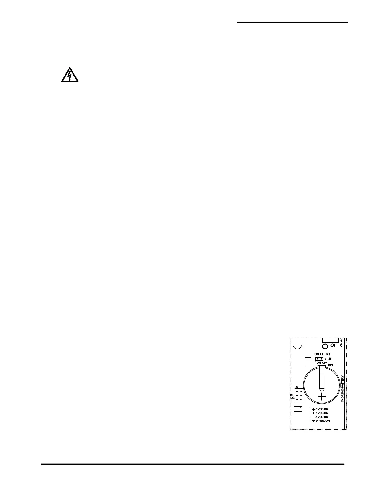
Battery BT1 on the PAL-AT system board maintains the clock settings when the
panel is off. Jumper J5, located above the battery, must be set “On” (left position)
to enable the battery. To test the condition of the battery on the system board, turn
off the power to PAL-AT for at least 60 seconds. Turn the power back on and check
the clock. If it has re-set to 00:00:00 01/01/13 then replace the battery.
The battery is 3 V type CR2025. It can be obtained locally or through PermAlert.
It is replaceable by gently lifting the retaining clip to remove the old battery and
sliding in the new one. Be careful to install the battery correctly. The lettering on
the battery (+) is facing out. Refer to this detail and figure 4-1.
Replace Battery With Energizer CR2025 Only. Use of Another Battery May Present
A Risk of Fire or Explosion.
Caution, Battery May Explode if Mistreated. Do Not Recharge, Disassemble or
Dispose Of in Fire.
 Loading...
