Output Relay System
56
ENTER RELAY NUMBER FOR SECTION ??:
* TO REENTER, # TO ACCEPT
CABLE ? SET FOR AUTOMATIC MO
CRI ? *FOR MENU, # TO CONTINUE
A.5 RS-232 Port Interface Cable Installation
The AT-ORC Output Relay Controller is provided with an RS-232 communications port and an interface
cable. The 9-pin male D connector on the interface cable connects to the Output Relay Controller RS-232
port. The other end of the cable connects to RS-232 Port 2 in the PAL-AT as follows:
Wire Color PAL-AT Port 2 Terminals
Red R2
White T2
Black GND
Additionally, a 2-pin shunt must be placed on the auxiliary header at position 2 (see section 4.5).
A.6 PAL-AT Control of Output Relay System
When the PAL-AT Leak Detection/Location system detects a leak or probe activation in a section of
sensing cable and that section has a control relay assigned to it, the PAL-AT communicates to the AT-
ORC Output Relay Controller and switches the SPDT output relay. The assigned control relay remains
switched until the alarm queue is cleared.
A.6.1 Sensing Cable and Probe Requirements
If sequential sections of sensing cable will control different relays, then the ends of the sensing cables
should be separated slightly from each other. This is required since there is a +/- 5 feet tolerance in
locating the leak. In this case, when assigning an output relay to a section of sensing cable, both the
start and end of the sensing cable should incorporate a 10-foot section of jumper cable (JMP-U) to
isolate the section. The two sections of JMP-U and the sensing cable will then be setup as one section
of sensing cable during the PAL-AT setup process. Probes will not need extra jumper cable.
A.6.2 Assign Output Relays
Follow the setup procedure detailed in section 2.1 of this manual. If the PAL-AT detects that an AT-ORC
Output Relay Controller is connected and powered, the setup function will include the following step. After
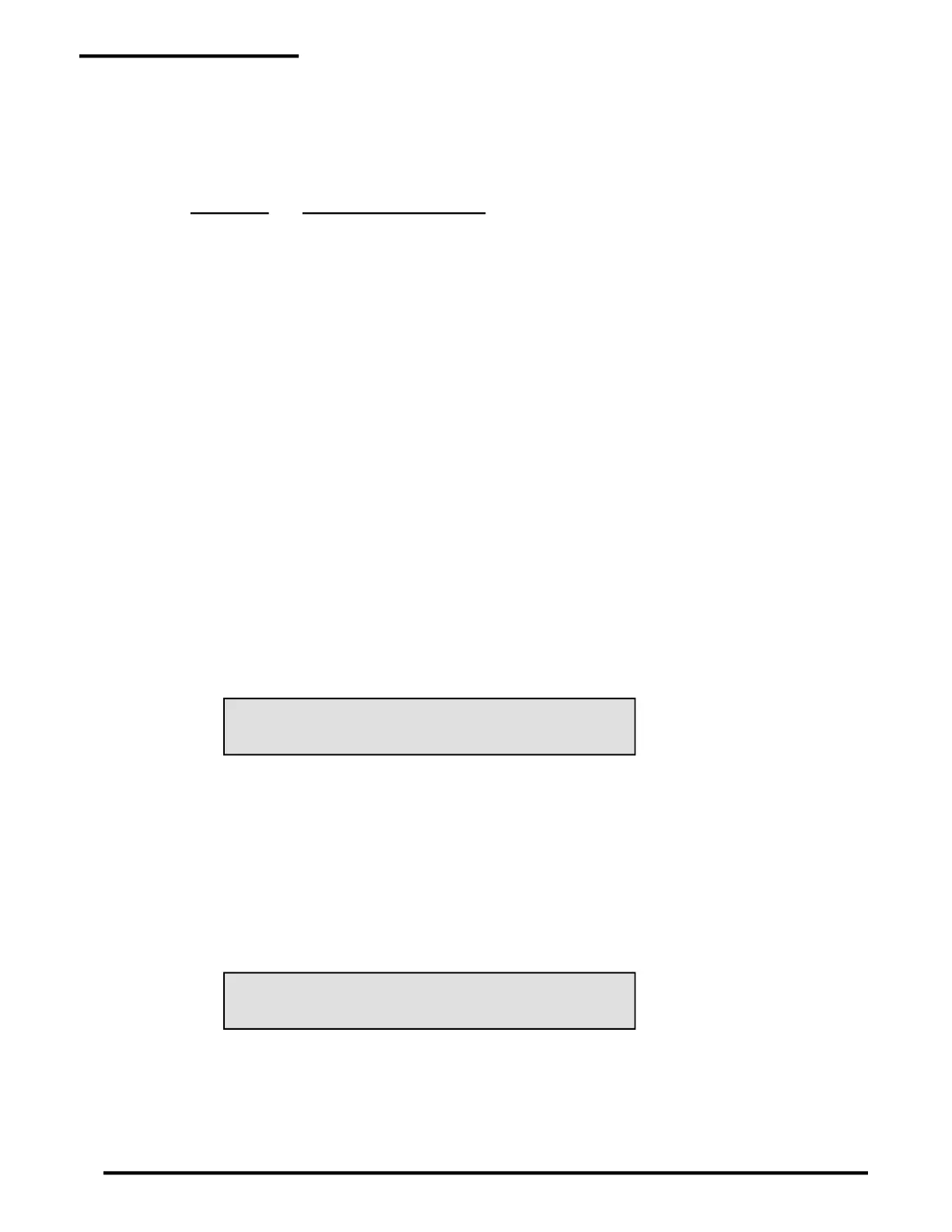
the distance is accepted for the section being setup, the PAL-AT displays:
LCDA-01:
Enter the number for the control relay that is assigned to the section that was just setup, and then press
the # key to accept the entered relay number. If no control relay is assigned to the section being setup
then just enter #. After the # key is pressed, the PAL-AT will prompt for the next section until the end of
setup is reached.
A.6.3 Display Output Relay Assignments
The control relay assignments can be viewed in the Display Setup Data function of the PAL-AT. Follow
the display setup procedure detailed in section 2.5. If the PAL-AT detects an AT-ORC Output Relay
Controller is connected and powered, after the end is displayed for the last section, the PAL-AT displays
the following or similar message:
LCDA-02:

 Loading...