PAL-AT Operating Manual
43
5 Troubleshooting
5.1 Initial Power-Up Checks
Warning - Before accessing the PAL-AT panel, the panel must be disconnected from the
power source and isolated from any hazardous voltage present in the panel, e.g. relay wiring.
Refer to the PAL-AT Installation Manual for wiring instructions. Refer all servicing to qualified
personnel.
Check the configuration of the power switches. Three internal switches on the system board control the
power source utilized by the panel. These switches are intended for use by service personnel. Set the AC
Power Switch (SW3) and the 24 VDC Power Switch (SW1) in the down, or “OFF” position. Next, set the
Input Power Select Switch (SW2) to either VAC or VDC depending on the desired power source. The panel
is controlled by SW3 for AC power or SW1 for DC power.
5.2 System Board
There are 3 different system boards. They can be identified by their serial numbers according to the
following table.
Serial Number PAL-AT System Figure
30XXXXXXX AT30C 1-1
31XXXXXXX AT75C 1-1
32XXXXXXX AT30K 1-2
A flexible flat cable from the label on the door connects to connector J3 on the system board to power the
front panel green LED, red LED and keypad.
The green LED flashes slowly whenever the system is not monitoring. In monitoring mode, it is on
continuously. The red LED is illuminated whenever any cable is in alarm. The red LED stays on until the
alarm queue is cleared and no cables are in alarm.
5.3 Diagnostic LEDs
There are several LEDs on the system board to indicate the status of components and to aid diagnosing
system problems. Refer to figure 4.1 for location of the LEDs on the system board. Models AT30C and
AT75C LEDs are located similarly.
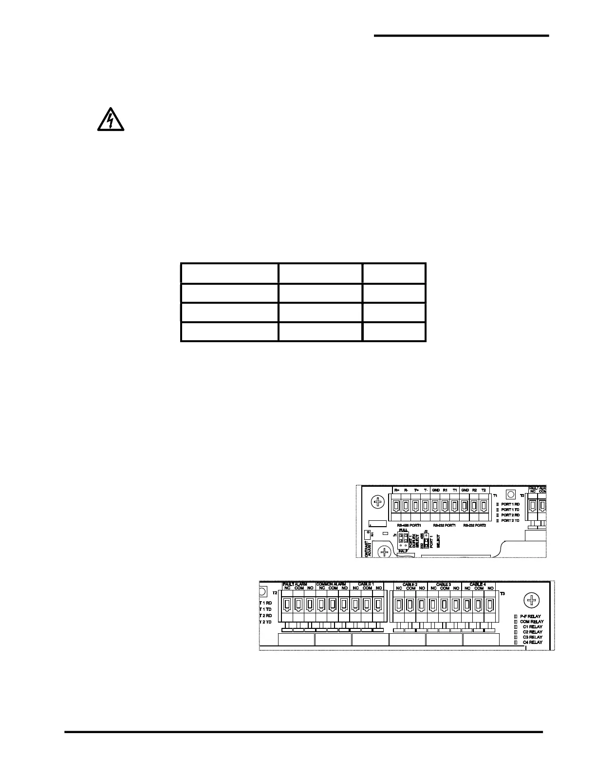
5.3.1 Port 1 and 2 RS-232/485
Four LEDs indicate data traffic on the 2 serial ports. Port 1
receive (RD) and transmit (TD) and port 2 receive (RD) and
transmit (TD). Receive LEDs are green and transmit LCDs
are yellow.
5.3.2 Relays
There are 3 (or 6) green LEDs to the
right of the relays, indicating relay
status. Each LED illuminated
indicates the corresponding relay is
energized. The operating mode of
the relays is controlled by firmware
(see section 2.9.1).

 Loading...