Output Relay System
54
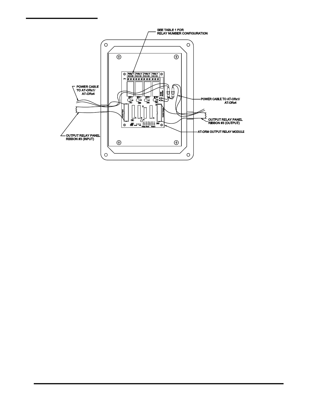
Figure A-3: AT-ORx1 Output Relay Panel Wiring Diagram
A.2 Relay Module Configuration
Each added AT-RM relay module must be configured before operating the system. Two jumpers are set
to select the numbers assigned to the 4 relays (1-4, 5-8, etc.). Locate the jumpers in the lower right corner.
The 60 relays are organized in 15 banks of 4. The first AT-RM is set to bank 1 and addresses relays 1 to
4. The Relay Number Select Jumper sets the module to address relays from 1-32 or 33-60. The Relay
Bank Select Jumper selects which group of 4 numbers to assign (5-8, 9-12, etc.). Labels are supplied to
renumber the relays. Place them over the relay label that is printed on the Relay Module circuit board.
Refer to Table A-1 for jumper settings.
 Loading...
