Adjustment
14 - 28
● Engage the stop motion device.
● Turn the drive pulley in its direction of rotation until the actuator projection is in its BDC.
● Hold the thread monitor finger forwards.
● Turn the handwheel until the switch function of the knife latch has been carried out.
● Turn the drive pulley in its direction of rotation until the knife latch has fallen into place
and the actuator projection is in its TDC.
● Loosen bolt 4 and move the stop 5 in accordance with requirement 1.
● Tighten bolt 4.
● Position finger 3 in accordance with requirement 2.
● Disengage the stop motion device.
● Mount lever 8 and circlip 6.
● Tighten screw 7.
6
8
7
2
3
1
5
4
0.5 mm
1.0 mm
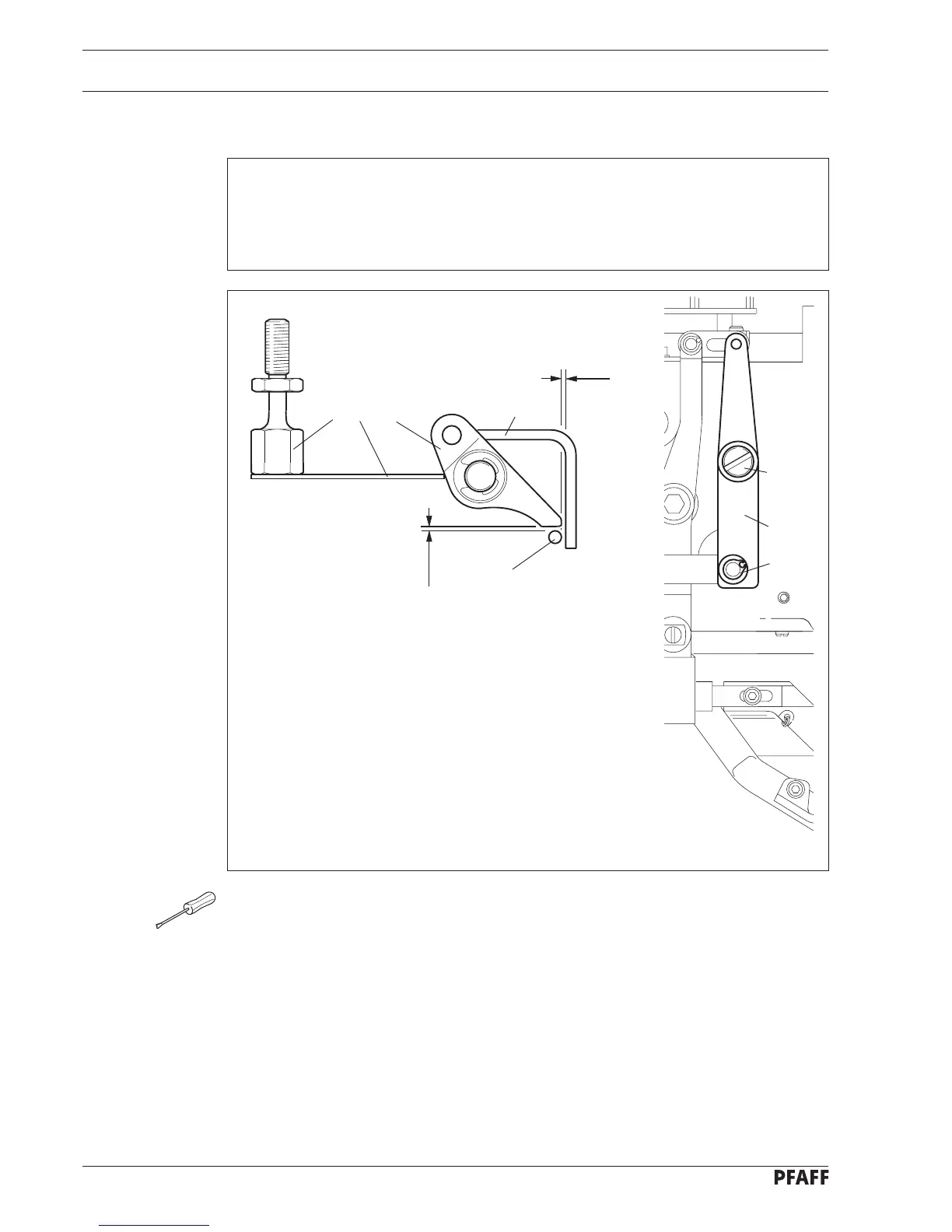
Fig. 14 - 26
14.12.05 Locking lever
Requirement
1. With the knife latch fallen and the actuator projection at its TDC there must be a
clearance of 1.0 mm between rod 1 of the knife latch and the locking lever 2.
2. In this position there must be a clearance of 0.5 mm between finger 3 and rod 1 of the
knife latch.