Adjustment
14 - 34
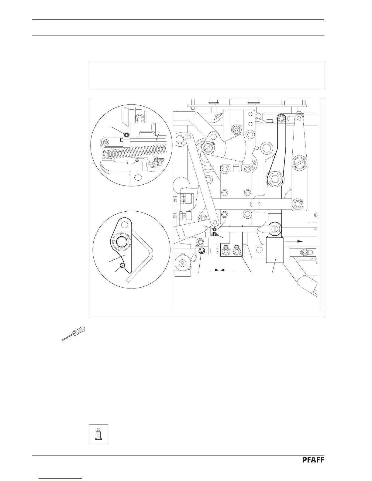
● Bring the machine to its program end position.
● Disengage the stop motion device.
● Loosen screws 3, 4, 5 and 6.
● Position rod 7 flush with the front end of the clamp piece 8 and tighten screw 3.
● In this position push guide 10 all the way up and move the rod 7 with the clamp piece 8
so that there is a clearance of approx. 2 mm between the guide 10 and the clamp
piece 8.
● Tighten screw 4.
● Pull lever 9 in the direction of the arrow until the locking lever 1 is touching the pin 2 of
the knife latch.
● Tighten screw 5.
The clamp piece 8 must be horizontal.
Screw 6 remains loosened for further adjustments.
2 mm
9
10
6
3
5
4
8
Fig. 14 - 32
2
7
1
14.12.11 Securing the knife
Requirement
With the stop motion device disengaged, the locking lever 1 must be touching the pin 2 of
the knife latch.