11 - 16
Adjustment
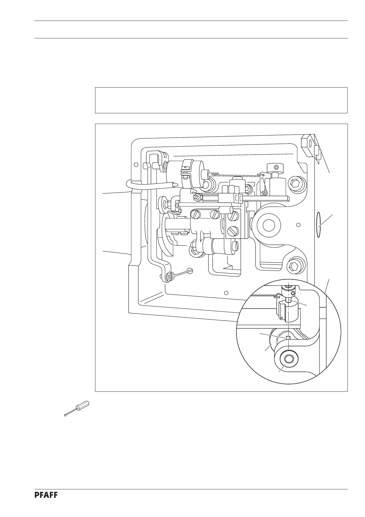
● Loosen the two screws on the control cam 2 through the assembly hole 1.
● Bring the take-up lever to its bdc by turning the handwheel .
● Turn the control cam 2 on its shaft in accordance with the requirement.
● In this position, and taking care to ensure that the control cam 2 is touching the
bearing 3 below it, tighten the accessible screw on the control cam 2.
● Make the second screw on the control cam 2 accessible and tighten it.
● Carry out a check.
11. 05 Adjusting the thread trimmer -900/52 (optional)
11. 05.01 Preadjusting the control cam
Requirement
With the take-up lever at its bdc, projection 4 on the control cam 2 must be directly
underneath the cam follower 5.
1
Fig. 11 - 15
5
3
2
4