11 - 18
Adjustment
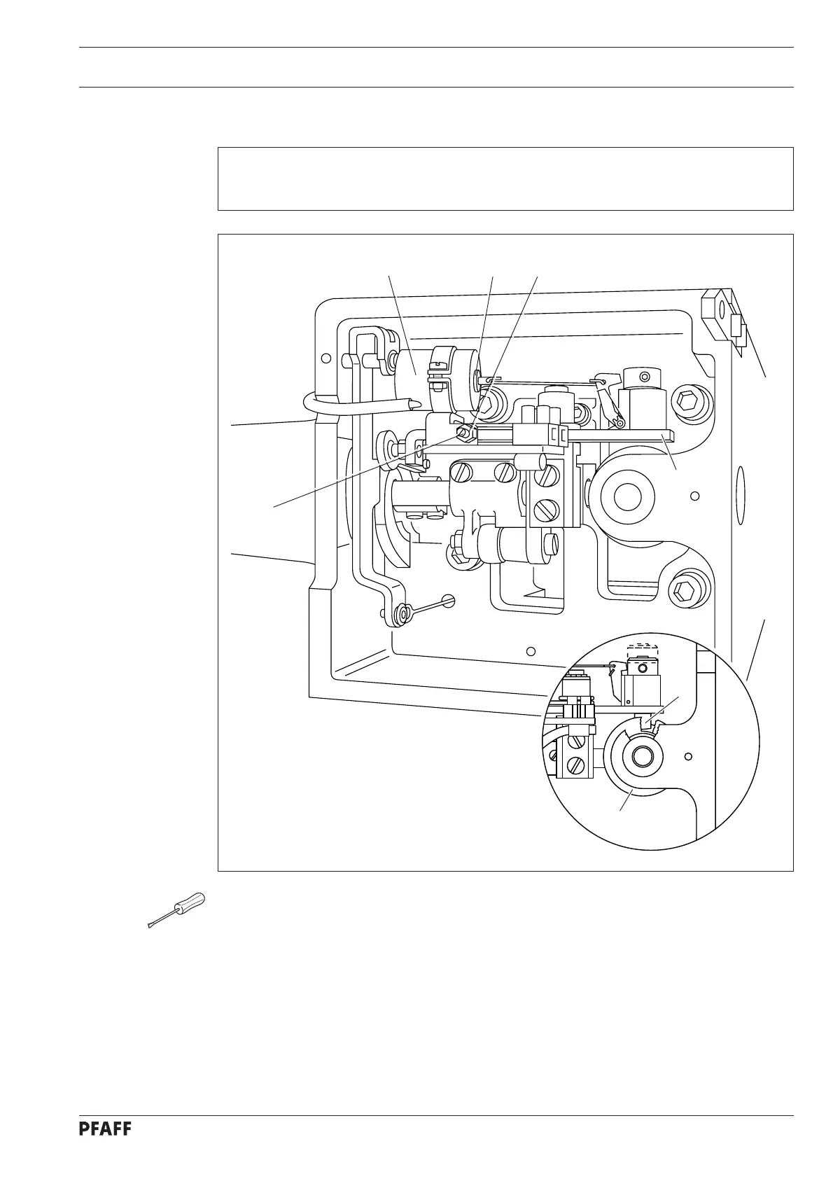
11. 05.03 Feed regulator pin
Requirement
With the needle bar at its bdc, the feed regulator pin 5 must be able to fall lightly into the
path of the control cam 7 when the engaging solenoid 6 is activated.
● Bring the needle bar to its bdc by turning the handwheel.
● Activate the magnet core 1 manually.
● Tighten locking screw 2 (nut 3) far enough so that it just touches the tripping lever 4.
● Loosen locking screw 2 approx. 1/2 a turn until the movement of the feed regulator pin 5
is in accordance with the requirement.
● Carry out a check.
Fig. 11 - 17
4
5
7
6
1
2
3