AC TRACTION – INSTALLATION PG DRIVES TECHNOLOGY
5.6 Control Connections Crimps and Tooling
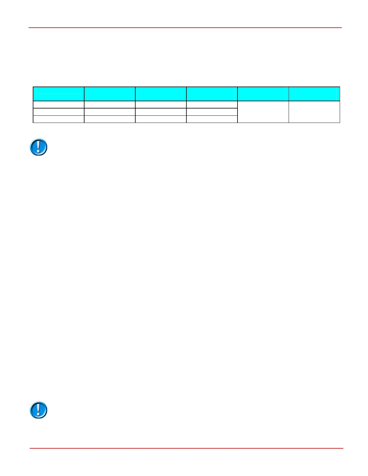
The following table shows the Molex part numbers for the mating crimps, housings, crimp tool and extraction tool.
Alternatively, the mating connectors can be purchased directly from PGDT using the connector kit part numbers shown.
Connector PGDT Connector
Kit Part No.
Molex Housing
Part No.
Molex Crimp
Part No.
Molex Crimp
Tool Part No.
Molex Extraction
Tool Part No.
A – 16-way D51066 43025-1600 43030-0007
B – 8-way D51068 43025-0800 43030-0007
C – 6-way D51067 43025-0600 43030-0007
69008-0982
11-03-0043
PGDT recommends that only genuine Molex parts should be used. Inferior quality crimps or
incorrect tooling can seriously reduce the reliability and longevity of the controller or vehicle.
PGDT accepts no liability for losses of any kind if non-recommended parts are used.
6 Connections
6.1 Battery Connection
Connect the positive supply to the B+ terminal and the negative supply to the B- terminal.
6.1.1 Power Fuse
A suitable fuse must be fitted to the battery positive supply. This fuse should be fitted as closely as possible to the battery’s positive
terminal.
6.1.2 Line Contactor & Pre-charge Resistor
A suitable line contactor must be connected to the battery positive supply. This should be fitted with a 5W 10kΩ pre-charge
resistor connected in parallel across the contacts. The coil of the line contactor can be controlled by the Sigmadrive, via pin 12
of Connector A.
6.1.3 Discharge Resistor
Units manufactured before October 2008 require an external discharge resistor. The resistor should be fitted between the
Sigmadrive’s B+ and B- terminals. The correct value for each controller model is shown below.
24V only Sigmadrive – 10kΩ 1/4W
24V – 48V Sigmadrive – 22kΩ 1/4W
72V – 80V Sigmadrive – 47kΩ 1/4W
6.1.4 Emergency Disconnect Switch
For certain vehicle types, safety legislation requires that an emergency battery disconnect switch or switches should be fitted in
the battery positive supply, in order to allow complete isolation of the vehicle’s electrical system from the battery. The location of
this switch or switches should be as stipulated in the appropriate legislative documentation.
It is the responsibility of the vehicle manufacturer to ensure appropriate fuses, line contactors
and emergency disconnect switches are used and that these devices are appropriately located.
PGDT accepts no liability for losses of any kind if inappropriate devices or arrangements are
used.
SK79646-01 18
 Loading...
