PG DRIVES TECHNOLOGY AC TRACTION – MOTOR SET-UP
:: Motor Driving Set-up Explained ::
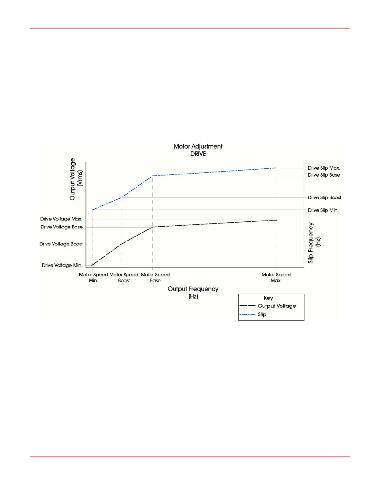
The graph below shows the twelve parameters that are involved in setting up the drive performance of the controller & motor
combination. Each of these parameters is explained in the following section.
The voltage and slip curves define the maximum permissible value for each, at a given motor stator (controller output)
frequency. The controller then, in response to Accelerator position and speed feedback from the Motor Encoder, adjusts the
voltage and slip values between their minimum and maximum values. The minimum voltage is 25% of the maximum motor
voltage, whereas the slip has a theoretical minimum of zero.
1.5 Motor Speed Minimum – (SPDmin)
This sets the minimum speed of the motor in both drive and braking scenarios.
A typical setting is between 1.0Hz and 2.0Hz.
The adjustable range is 0Hz to 63Hz in 0.0625Hz steps.
1.6 Motor Speed Boost – (SPDboost)
To compensate for stator voltage drops at low frequencies, the controller is able to supply a ‘boost’ voltage, between 4.5 Motor
Speed Minimum and the speed set by this parameter.
The adjustable range is 0Hz to 255Hz in 1Hz steps.
SK79646-01 57

 Loading...