FL SWITCH LM ...
6-8
PHOENIX CONTACT 7278_en_04
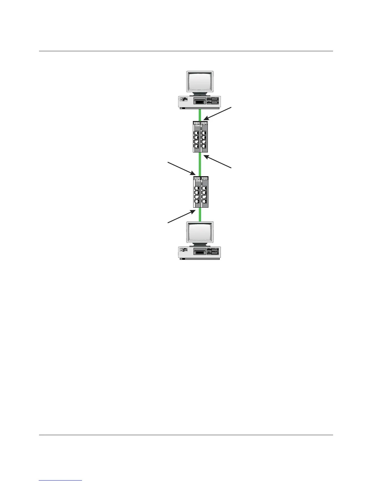
Figure 6-6 Example: Communication between termination devices via VLAN
Switch configuration
1 Set both switches to "VLAN Tagging" mode, save, and restart devices.
2 Create VLAN 5 on switch 1 and specify port 7 as an "untagged" member and port 1 as
a "tagged" member.
3 For port 7 at switch 1, set the port VLAN ID to 5 and the port priority to any.
4 On switch 2, create port 2 and port 3 as "tagged" members of VLAN 5.
Both termination devices now communicate via the network path shown in the example
without other switch ports forwarding the broadcast packets for both termination devices, for
example.
6.6 VLAN and (R)STP
When using (R)STP and VLAN simultaneously, please note the following:
–(R)STP is not based on VLANs
– (R)STP creates a loop-free topology in the form of a tree structure
Device B
participant in VLAN 5
without Tags
Device A
participant in VLAN 5
without Tags
Switch 1
Port 7
VID 5, Prio 4
participant VLAN 5
without Tags
Switch 1
Port 1
VID X, Prio X
participant VLAN 5
with Tags
Switch 2
Port 2
VID X, Prio X
participant VLAN 5
with Tags
Switch 2
Port 3
VID X, Prio X
participant VLAN 5
with Tags
FL SWITCH 5TX
Ord.No.2832085
US1
US2
FL SWITCH LM 8TX
Ord.-No.2832632
1
2
3
4
5
6
7
8
FL SWITCH 5TX
Ord.No.2832085
US1
US2
FL SWITCH LM 8TX
Ord.-No.2832632
1
2
3
4
5
6
7
8
72780018