Rapid Spanning Tree
7278_en_04 PHOENIX CONTACT 4-11
– Possible to check whether the desired topology corresponds to the actual topology.
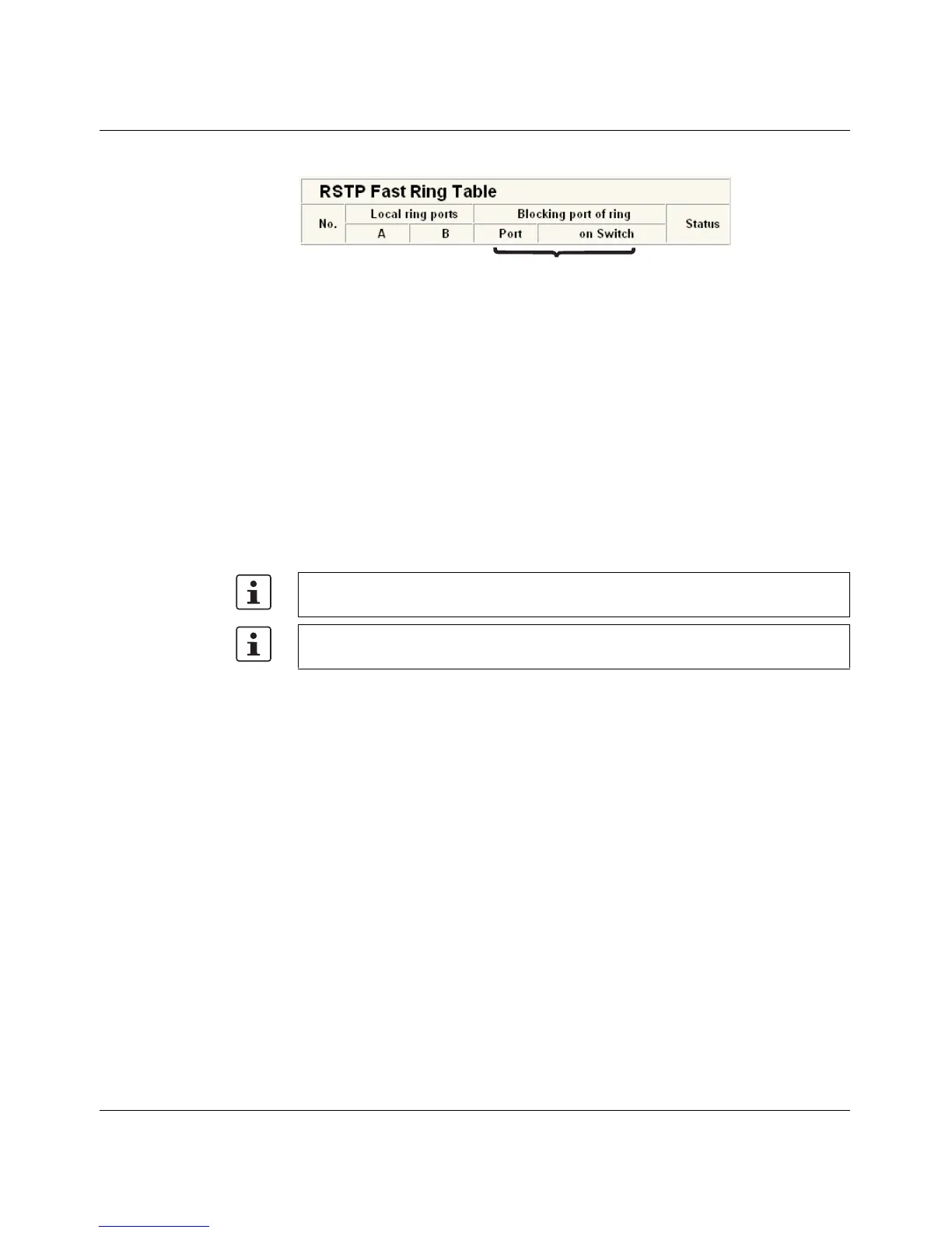
Figure 4-9 RSTP Ring Table
Information in WBM The following information is displayed on the web page (and via SNMP):
Local ring ports
These two ports of this switch belong to the ring that is listed (ring ID).
Blocking port
This port deliberately breaks the loop.
Ring detection states The following states can occur for ring detection:
– Not Ready - Ring detection has not yet been completed.
– OK - Ring detection has been completed and quick switch-over is possible in the event
of an error.
– Breaked - The ring is broken on this branch in the direction of the root switch.
– Failed on Port A - The ring was broken on this switch at port A.
When using RSTP fast ring detection, please note the following:
– For RSTP fast ring detection, do not use devices that do not support this function.
– Enable RSTP fast ring detection on all devices.
– All data paths must be in full duplex mode.
4.2.2.1 Fast ring detection switch-over times
With the maximum permissible number of 57 switches in a ring, typical switch-over times
range from 100 to 500 ms with fast ring detection.
4.2.3 Connection failure - Example
The following diagram illustrates an RSTP ring with six switches, where switch 1 is the root.
The ring extends over port 1 and port 2 for each switch. On switch 4, the loop is broken by
a blocking port.
If a cable interrupt occurs at the point indicated by the star, this produces the following
entries on the "RSTP Fast Ring Detection" web page:
Switch 3 - Failed on Port A
Ring ID
In the event of a link failure in the ring, the "trapRstpRingFailure" trap is sent.
If "Breaked" or "Failed" status lasts for longer than 60 seconds, it is no longer displayed
after the next topology modification, since these rings no longer exist.