Lean Managed Switch
7278_en_04 PHOENIX CONTACT 1-7
1.3 Installing the Lean Managed Switch
1.3.1 Connecting the supply voltage
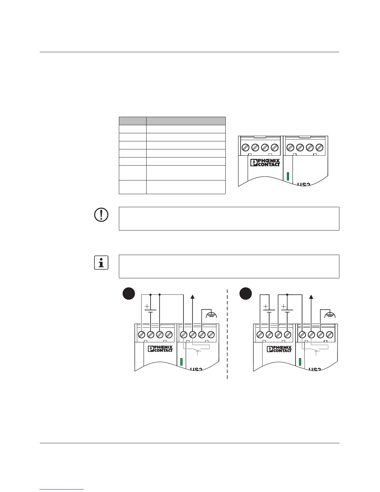
1.3.1.1 Assignment of the COMBICON connector
24 V DC The LMS is operated with a 24 V DC voltage that can be supplied redundantly, if required
(see Figure 1-6 version 2)
Figure 1-6 LMS supply
Terminal Meaning
1 Supply voltage +US1
2GND US1
3 Supply voltage +US2
4GND US2
5 and 6 Floating alarm contact
7 Functional earth ground
(optional)
8Not used
U S 1
1 8765432
6 5 7 0 0 0 6
NOTE: The switch is designed for SELV/PELV operation at +24 V DC according to
IEC 60950-1/VDE 0805. Only SELV/PELV according to the defined standards may be
used for supply purposes.
If redundant power supply monitoring is active (default setting), an error is indicated if only
one voltage is applied. A bridge between US1 and US2 prevents this error message. It is
also possible to deactivate monitoring in web-based management.
US1
OUT
24 V DC
opt.
US1
OUT
24 V DC
opt.
12