FL SWITCH LM ...
1-8
PHOENIX CONTACT 7278_en_04
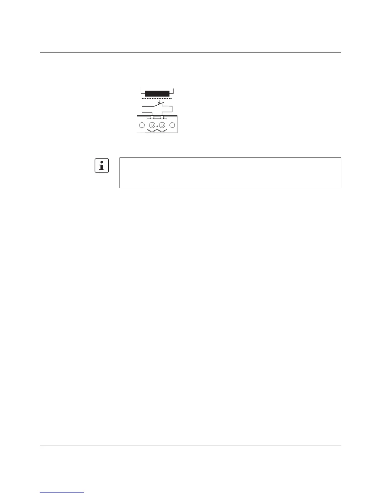
1.3.2 Alarm contact
The switch has a floating alarm contact. An error is indicated when the contact is opened.
Figure 1-7 Basic circuit diagram for the alarm contact
R 1 R 2
6 7 8 4 0 0 1 5
In the event of non-redundant power supply, the switch indicates a supply voltage failure
by opening the alarm contact. This error message can be prevented by connecting the
supply voltage to both terminals in parallel, as shown in Figure 1-6, or by deactivating
redundant power supply monitoring in web-based management.