Startup and functions
7278_en_04 PHOENIX CONTACT 2-3
The bits for the network class are followed by those for the network address and the user
address. Depending on the network class, a different number of bits are available, both for
the network address (network ID) and the user address (host ID).
IP addresses can be represented in decimal or hexadecimal form. In decimal notation,
bytes are separated by dots (dotted decimal notation) to show the logical grouping of the
individual bytes.
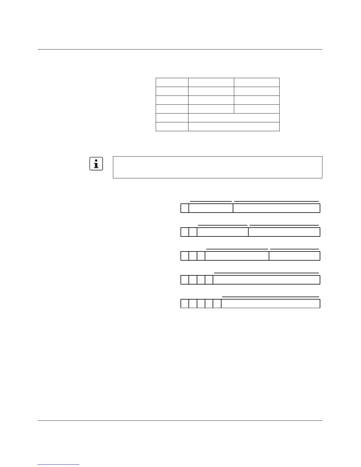
Possible address combinations
Figure 2-2 Structure of IP addresses
Network ID Host ID
Class A 7 bits 24 bits
Class B 14 bits 16 bits
Class C 21 bits 8 bits
Class D 28-bit multicast identifier
Class E 27 bits (reserved)
The decimal points do not divide the address into a network and user address. Only the
value of the first bits (before the first "zero") specifies the network class and the number of
remaining bits in the address.
7 bits
24 bits
14 bits 16 bits
21 bits
8 bits
28 bits
27 bits
Network ID
Host ID
Host ID
Host ID
Network ID
Network ID
0
0
0
0
0
1
11
111
1111
Class A
0.0.0.0 - 127.255.255.255
Class B
128.0.0.0 - 191.255.255.255
Class C
192.0.0.0 - 223.255.255.255
Class D
224.0.0.0 - 239.255.255.255
Class E
240.0.0.0 - 247.255.255.255
Identifier for multicast group
Reserved for future applications