43
5277A
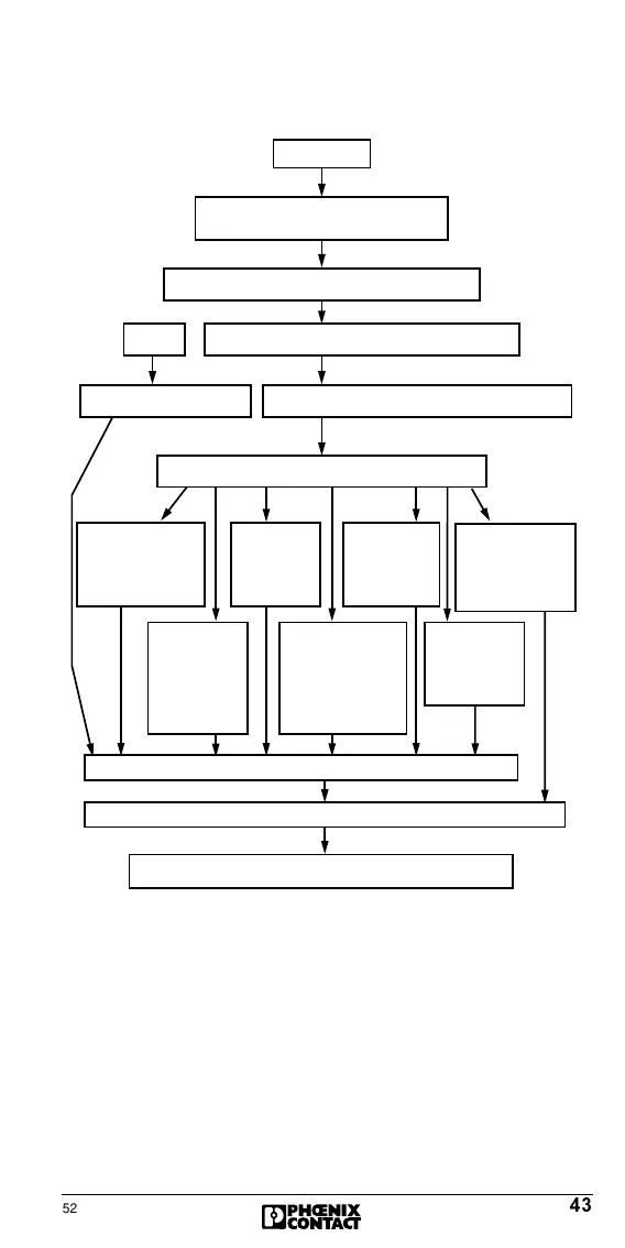
Flowchart for Error Recovery
Figure 30: Flowchart for error recovery
The diagnostic behavior of the controller board can be divided
as follows:
1. Recognition of operating and faulty states;
automatic diagnostics
2. Display of diagnostic data via the:
- Front panel (error group and parameter via LCD)
3. Extended diagnostic functions via the driver software sup-
plied or the RS232/V24 interface with the IBS CMD SWT
G4 software tool.
Error occurs
5277A005
Error is indicated: - LC Display
- Software function
LCD displays: Error group, segment/position, code
RB, LB, BUS, OUT1, OUT2, PF, DEVCTRL
Segment/Position and error code are displayedFirmware or hardware error
Checking the faulty bus segment
Message:
RB
Error in remote bus
cabling, supply of
bus terminal modules
(BK), ...
Message:
LB
Error in local
bus cabling
I/O module
Message:
BUS
Error location is
not clearly de-
fined, an area
is limited.
Message:
OUT1
Seg./Pos. of the
interface as of
which the error
occurs.
Messge:
OUT2
Seg./Pos. of
BK module as
of which the
error occurs.
Message:
DEV
No transmission
error. Error is detec-
ted in the device it-
self and indicated in
the display of the
controller board.
Maintain system
Delete error display: Via application program
Bus is in stop state. All outputs are reset!
Message:
PF
Peripheral fault
Attention:
Bus continues to run
 Loading...