© PSI (Photon Systems Instruments), spol. s r. o.
56
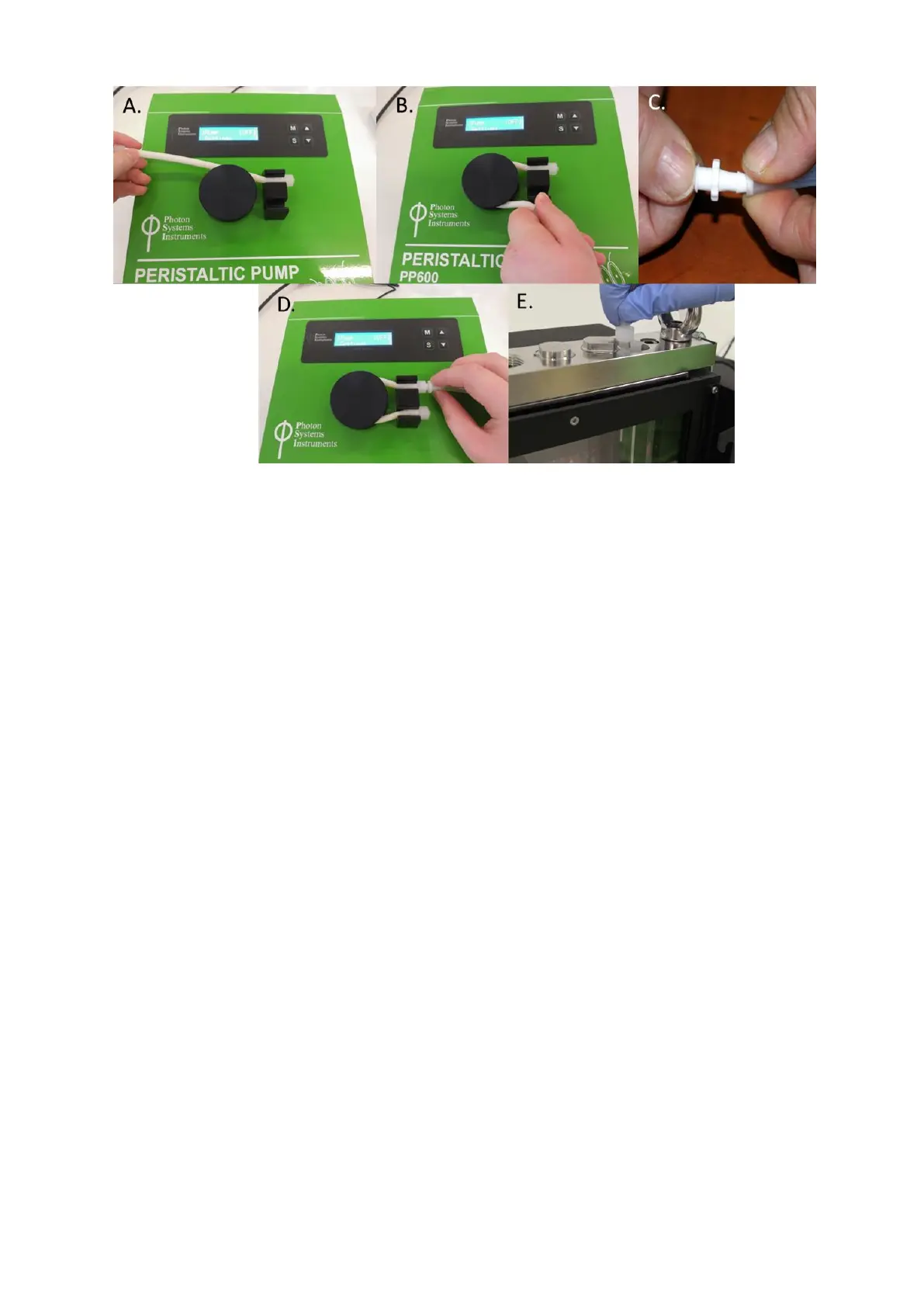
Fig. 47 Assembly of the peristaltic pump. A, B) Short tube is attached around the rotor wheel to the peristaltic pump. C, D) Adapter is
attached to the silicone tubing and connected with the tubing of the peristaltic pump. E) Tubing from the peristaltic pump is connected
with the cultivation vessel.
• Attach provided female luer connector to the silicone tube and connect it to the peristaltic pump as shown in Fig.
47C,D. Again, ensuring that the tubing is pushed all the way to the end of the luer lock connector.
• Connect the free end of the silicone tube via Male Luer Lock Fitting with the lid of the cultivation vessel (Fig. 47E).
The position for connection on the vessel lid corresponds to the position of outlet n°6 in Fig. 13C.
• Attach a new piece of tubing to another female luer connector and attach it to the Peristaltic Pump as shown in
Fig. 48A.
• Place the other end of this tubing in the suspension or medium (Fig. 48B) depending on the application of the
pump.