© PSI (Photon Systems Instruments), spol. s r. o.
57
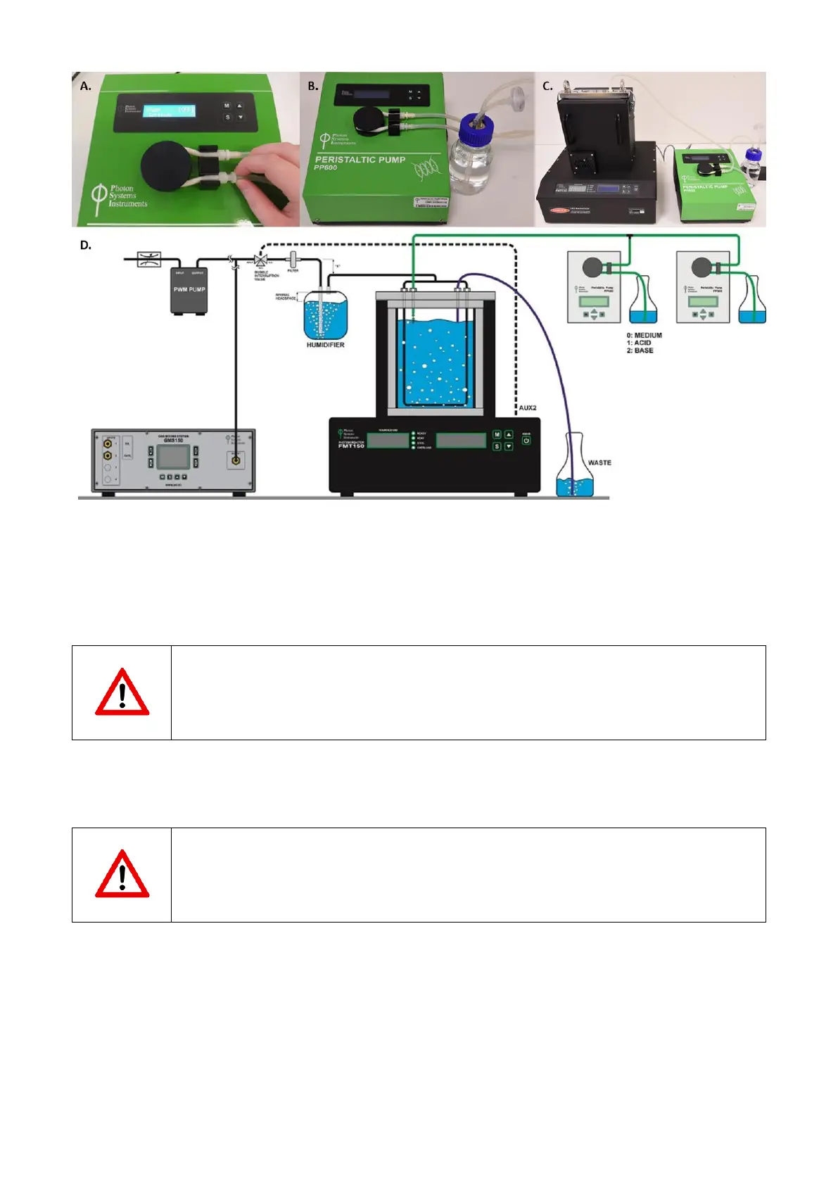
Fig. 48 Final assembly of the peristaltic pump. A) Second luer connector is attached. B) Connection of the silicone tubing with the
medium for the cultivation. C) Fully installed peristaltic pump tubing. D) Schematic representation of PBR FMT150 unit connected to
peristaltic pumps in chemostat and turbidostat mode and to GMS 150.
• Connect the silicone tubing from the peristaltic pump to the vessel lid. Peristaltic pump tubing is attached to the
outlet for the sampling tube (n°6 in Fig. 13A,C). Please refer to Fig. 48D for schematic representation of the PBR
FMT150 set-up when peristaltic pump module and GM module is included.
Important note: Please note that the vessel lid assembly is different if peristaltic pump is used together
with the Gas Analysis module. Please refer to page 53 and Fig. 44 for further instructions.
• Install the wiring connections for the peristaltic pump as shown in Fig. 49.
• Connect the Photobioreactor and the Peristaltic Pump using provided communication cable.
Important note: Please note that the communication connection scheme with the PBR FMT150 varies
depending on the complete set-up of the system. Please refer to page 22 Fig. 10 for schematic
representation of different connection set ups based on the system composition.
• Plug one end of the communication cable into the “AUX IN” connector of the Peristaltic Pump (Fig. 49A).
• Plug the other end of the cable into the “AUX 1” or other available AUX connectors at the rear of the
Photobioreactor (Fig. 49B). Please refer to page 22 for further information.
• Connect the Peristaltic Pump via the power supply cord into the “POWER” connector of the Peristaltic Pump (Fig.
49C).
• See Fig. 50D for complete setup of the Peristaltic Pump.